An excavator pressure sensor fault can appear as a warning code, an implausible live-data value, weak hydraulic response, engine derate or a no-start condition. None of those observations proves that the sensor itself has failed. A damaged connector, an open or shorted circuit, a poor ground, a shared reference-voltage problem, real system pressure outside the expected range or incorrect controller data can produce a similar result.
The replacement decision should therefore follow an evidence chain. First identify the system and exact sensor. Then confirm the circuit, compare electronic data with an independent or manufacturer-approved reference, and reconcile the old and proposed parts. This guide gives repair workshops and parts buyers a practical record for doing that without inventing a universal pinout, voltage, pressure range, thread or torque value.
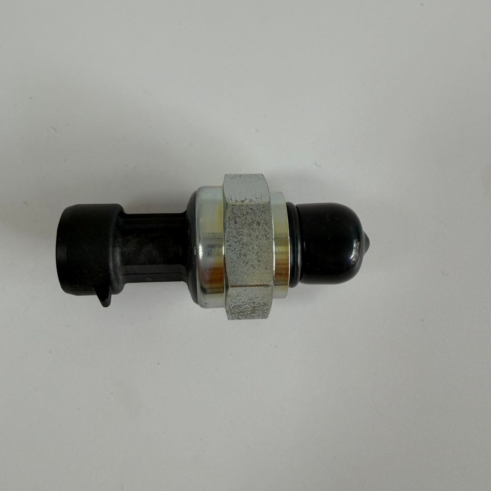
A fault code is a starting point, not a parts verdict
A controller usually detects a circuit or plausibility problem; it does not perform a physical teardown of the sensor. The diagnostic record may indicate that a signal is high, low, intermittent, out of range or inconsistent with another operating condition. Those labels help choose tests, but they do not separate a failed sensing element from a harness fault, supply problem or genuine pressure condition.
Record the full code and description, controller, occurrence count, active or logged state, operating condition and related codes. Save a screenshot or service-tool report before clearing anything. If several sensors that share a supply or return circuit fail together, the common circuit deserves attention before individual parts are ordered. The applicable machine and engine documentation controls the test points and acceptance limits.
First identify which pressure the machine is measuring
“Pressure sensor” is a function class, not a complete identity. A hydraulic or pilot-pressure transducer, a common-rail fuel-pressure sensor and an engine-oil-pressure sensor work in different media and systems. Connectors that look alike can still have different terminal assignments, calibrations, sealing arrangements and controller expectations. A pressure switch also provides different information from a proportional sensor.
| Sensor group | What the controller may use it for | Evidence required before replacement | Do not assume |
|---|---|---|---|
| Hydraulic or pilot pressure | Control demand, pump regulation, function monitoring or diagnostics | Hydraulic circuit location, machine serial, sensor marking, connector, wiring diagram and pressure-test method | That every similar body uses the same port, range or pinout |
| Common-rail fuel pressure | Fuel-pressure feedback and system plausibility checks | Engine identity, rail location, service data, commanded versus actual pressure and safe electrical test plan | That a rail-pressure code proves the sensor is faulty |
| Engine oil pressure | Lubrication monitoring, warning strategy or engine protection | Engine serial, sensor or switch type, independent pressure evidence and circuit checks | That an electrical value proves actual oil pressure is safe |
| Pressure switch | State change above or below a specified threshold | Switch function, state table, connector and manufacturer threshold/test method | That it can replace a proportional transducer |
Do not open a hydraulic or common-rail connection simply to see whether pressure is present. Stored high-pressure fluid can penetrate skin, and common-rail fuel systems require model-specific depressurization and service procedures. The UK Health and Safety Executive’s guidance on hydraulic injection injury explains why suspected pinhole leaks must never be searched for by hand.
Watch an excavator pump-pressure sensor case
The video below follows a Kobelco excavator with slow operation and fault code 0024 associated with the pump 2 pressure sensor. It is directly relevant to excavator hydraulic diagnosis because the complaint, controller code and pressure-sensor circuit belong to an excavator pump-control system. Use it as a field case showing why the code and machine behavior must be investigated together.
Do not transfer the video’s code or test values to another excavator. Confirm the code description, connector and circuit in the applicable Kobelco manual for the machine serial number. For the separate common-rail branch of this article, Pico’s Bosch common-rail pressure guided test begins by identifying the output circuit from manufacturer data. Its heavy-duty and off-highway leakage test also warns that the method may not apply to every vehicle.
Build the diagnostic evidence ladder
1. Preserve the complaint and controller evidence
Interview the operator and record when the problem occurs: key-on, starting, warm idle, travel, digging, combined functions or shutdown. Note recent washing, harness work, engine or hydraulic repairs and component replacement. Collect all related codes and live-data channels, not only the first pressure value that looks wrong. A repeatable condition is easier to test than a broad statement such as “the sensor is bad.”
2. Prove component identity before probing
Photograph the machine plate, engine plate when relevant, installed location, connector face, wire colors and routing, sensor body, wrench hex, pressure end, seal and every readable marking. Search the correct parts information by the complete machine or engine serial. If the old part number is missing, dimensions and photographs can support an inquiry, but they cannot establish electrical calibration.
3. Inspect the connector and harness under real conditions
Look for oil or water ingress, corrosion, spread or pushed-back terminals, missing seals, damaged locks, rubbing, unsupported weight, heat exposure and repairs hidden under tape. Inspect the harness from the sensor toward the controller and any shared splice or reference circuit identified in the wiring diagram. Flex or vibration testing should follow a safe, controlled method; do not pull on individual wires or pierce insulation casually.
4. Verify supply, return and signal from the correct diagram
Determine whether the component is an active sensor, passive sensor or switch and identify each terminal from service data. Test the supply and return under the specified connected or disconnected condition. Measure voltage drop or circuit integrity using a method that does not damage terminals. Fluke’s automotive multimeter guidance recommends consulting the service manual for target values, back-probing where possible, disconnecting power for resistance or continuity tests and documenting results.
A voltage seen on an unplugged connector is only one observation. The circuit may fail under load, share a disturbed reference with another sensor or have a return offset that changes the signal. Compare the measured values at the sensor and controller only where the wiring diagram and service process call for it.
5. Compare electronic data with physical system evidence
For a hydraulic or oil-pressure complaint, use the approved mechanical or calibrated reference method at the specified point and operating condition. For common rail, keep the high-pressure system closed and use the engine maker’s approved electronic and pressure-test process. Compare requested and actual data, signal behavior and independent evidence as a group. If actual pressure is genuinely wrong, replacing the sensor may hide the diagnostic path without correcting the machine.
6. Make the replacement decision from converging evidence
A stronger decision has at least two supporting observations: correct supply and return, intact circuits, implausible or non-responsive signal, disagreement with a trusted reference, and a known-good comparison performed under an approved procedure. Record why the sensor was condemned and what alternative causes were excluded. Controlled substitution can be useful, but only with a correctly identified part and without using the new component as an uncontrolled test tool.
| Finding | Likely next step | Replacement status |
|---|---|---|
| Supply or return is outside the service specification | Diagnose shared supply, ground, connector and harness before the sensor | Hold |
| Signal changes when the harness is moved | Locate terminal, splice or conductor fault and verify the repair | Hold |
| Electronic value disagrees with an approved independent reference | Verify test setup, circuit and calibration, then assess the sensor | Conditional |
| Electronic and physical evidence both show real pressure loss | Diagnose the hydraulic, lubrication or fuel system cause | Hold unless sensor evidence also fails |
| Correct circuits plus repeatable implausible sensor response | Complete identity and fitment reconciliation | Release after written match |
Turn the workshop record into a supplier-ready RFQ
The Hongtengda excavator sensor category currently groups multiple sensor functions, so a category name alone is not enough for selection. Three current inquiry examples show why the system must be stated: a Hitachi EX-series pressure sensor listing, a CAT C7.1 common-rail pressure sensor listing, and a CAT C7.1 engine-oil-pressure sensor listing. These links are identification starting points. Their titles do not prove interchangeability or fitment for another serial range.
| RFQ field | Buyer evidence | Supplier confirmation requested |
|---|---|---|
| Machine and engine identity | Brand, model, full serial or prefix, engine model and plate photos | Exact application basis repeated on the quote |
| Sensor identity | All markings, installed location, function and old invoice if available | Quoted number and cross-reference basis |
| Mechanical interface | Overall photos, pressure end, seal, thread measurements and hex dimensions | Annotated dimensional and sealing match |
| Electrical interface | Connector face, keying, pin count, wire colors and service-diagram reference | Connector and electrical function match; no guessed pinout |
| Diagnostic basis | Codes, live-data captures, circuit readings and independent pressure evidence | Any additional pre-installation check required |
| Commercial scope | Required sensor, seal, connector repair part and quantity | Included and excluded items, packaging identification and document set |
Use a receiving and installation gate
Keep the old and new sensors side by side before removing protective caps. Compare the quoted number, connector keying, terminal count, body and hex geometry, pressure interface and supplied seal. A connector that plugs in does not confirm the signal type or calibration. Resolve any difference in writing before installation.
- The supplier’s selection matches the recorded machine or engine serial and sensor function.
- The old and new markings, connector face and mechanical interfaces are documented.
- The required seal is correct for the application and the pressure port remains clean and protected.
- Installation torque, seal treatment and orientation come from the applicable service instructions.
- Harness damage and shared supply or ground faults found during diagnosis have been corrected.
- The post-installation test condition and expected live-data behavior are defined before startup.
- Old fault data, test readings, receiving photographs and supplier confirmation remain with the work order.
Close the job with a replacement release record
After installation, inspect for leakage without touching a suspected pressurized leak, reconnect the harness securely and run only the manufacturer-approved commissioning checks. Confirm that the original symptom is gone, the signal responds plausibly, related fault codes do not return and the physical pressure condition is safe. If the data remains wrong, stop and return to the circuit and system evidence rather than fitting another sensor.
For a written excavator pressure sensor fault and fitment review, send Hongtengda the machine and engine plates, old sensor markings, connector-face and installed-location photographs, full fault report, live-data capture, circuit readings and approved pressure-test results. That package gives the supplier a defensible basis for identifying the part and gives the workshop a clear record of why replacement was released.