A slow excavator is often blamed on the main hydraulic pump, but the pump control can be the component that is failing to command displacement correctly. The regulator reacts to pressure and demand signals, moves control spools, and changes the pump’s swash-plate position. A fault in the signal circuit, pilot supply, solenoid, oil condition or downstream hydraulics can produce the same complaint. This field guide organizes excavator main pump regulator failure diagnosis before a replacement is ordered.
Translate the complaint into a control response
Write down whether the machine is weak, slow, unstable, overloaded or different between functions. Note engine speed, oil temperature, work mode and whether the problem affects one pump section or the entire machine. A regulator that does not stroke the pump can limit flow. A regulator that commands too much displacement can load or stall the engine. Hunting or delayed response may come from a sticky spool, unstable signal or aerated oil. None of these patterns proves that the regulator itself is defective.
Danfoss lists pilot pressure, control settings, load-sense signals, external valving, inlet conditions and internal leakage among checks for sluggish or unstable open-circuit pump response in its D1 pump service manual. The manual supports the test sequence, while the excavator service data controls actual pressures and adjustments.
| Machine behavior | Regulator-related possibility | Other causes to separate |
|---|---|---|
| All functions slow | Pump remains partly destroked | Low pilot supply, low engine speed, inlet restriction |
| Engine loads heavily | Torque or power control not responding | Mechanical engine fault, relief setting, excessive load |
| Response surges | Sticky control spool or unstable feedback | Air in oil, intermittent electrical command, valve chatter |
| One function weak | Signal reaching the control may be incorrect | Main valve, local relief, cylinder or motor leakage |
Isolate stored pressure and protect cleanliness
Lower the attachment, stop the engine, isolate starting, release stored pressure by the exact machine procedure and clean the work area. The HSE warns that high-pressure hydraulic fluid can penetrate skin; its hydraulic fluid safety guidance also emphasizes safe isolation and proper leak detection. Never loosen a regulator plug or hose to see whether pressure is present.
Before opening any line, photograph and tag every hose and connector. Cap both sides immediately. The small passages and spool clearances in a pump control are sensitive to contamination. Record any damaged seals, metal particles, varnish or sludge, because a new control installed into a contaminated system can repeat the failure.
Measure inputs before touching an adjustment
Follow the hydraulic schematic from the main valve or controller to the regulator. Identify pilot, load-sense, power-control and drain connections for the exact pump. Install approved gauges at specified test points and record oil temperature, engine speed, mode and control position. Compare neutral, a defined working command and the affected function against an unaffected function.
Do not turn an adjustment screw as a diagnostic shortcut. Danfoss explains how pressure-compensated and load-sensing controls react to system and load-sense pressure in its Series 45 pump control information. That principle helps interpret feedback, but its settings do not transfer to a Hitachi pump. Preserve every original setting and use only the specified procedure.
| Input or condition | What to record | Decision value |
|---|---|---|
| Engine input | Actual speed and load response | Prevents a power-source problem being blamed on hydraulics |
| Pilot/control pressure | Neutral and commanded readings | Shows whether the regulator receives a usable command |
| Load-sense signal | Signal stability and comparison | Separates feedback loss from regulator motion |
| Electrical command | Supply, ground and commanded output where applicable | Separates controller or harness faults |
| Oil and inlet | Temperature, level, aeration and restriction evidence | Identifies conditions that imitate control failure |
Separate the regulator from the pump and system
If input signals are correct but pump response is not, inspect the control spool and linkage only as the service manual allows. A sticky spool, damaged spring, blocked orifice, worn feedback part or internal leakage may prevent correct response. A worn rotating group can also fail to produce flow even when the regulator moves correctly. Parker’s variable-pump troubleshooting manual illustrates why charge supply, actuator condition, command input, temperature and case pressure must be considered together.
A controlled comparison is stronger than a single pressure reading. If the machine has tandem pump sections, compare their command signals and output under the same test. Confirm the main valve and relief paths are not diverting flow. Inspect case-drain condition only with the equipment and limits specified by the manufacturer. Stop testing if noise, temperature or pressure becomes abnormal.
Build a fault-isolation matrix before removing parts. For example, if both pump sections receive correct signals but only one responds poorly, compare that section’s regulator and rotating group. If both sections behave alike, look for shared pilot supply, controller command, engine input or oil-condition causes. If the complaint appears only during combined functions, record which command changes the load-sense or power-control signal. This method turns a vague “weak hydraulics” report into repeatable evidence.
Oil temperature must be treated as a test condition rather than an afterthought. Cold viscosity can slow a control spool, while hot oil can increase leakage through worn clearances. Record the same points during a controlled cold check and after the system reaches the manufacturer-defined test condition. Do not create heat by holding an actuator against relief longer than the procedure permits.
The video above is explicitly about fitting a hydraulic pump regulator on a Hitachi ZX200 excavator. It helps identify the component and installation context; it is not a substitute for the correct service procedure or calibration data.
Build an interface-based regulator RFQ
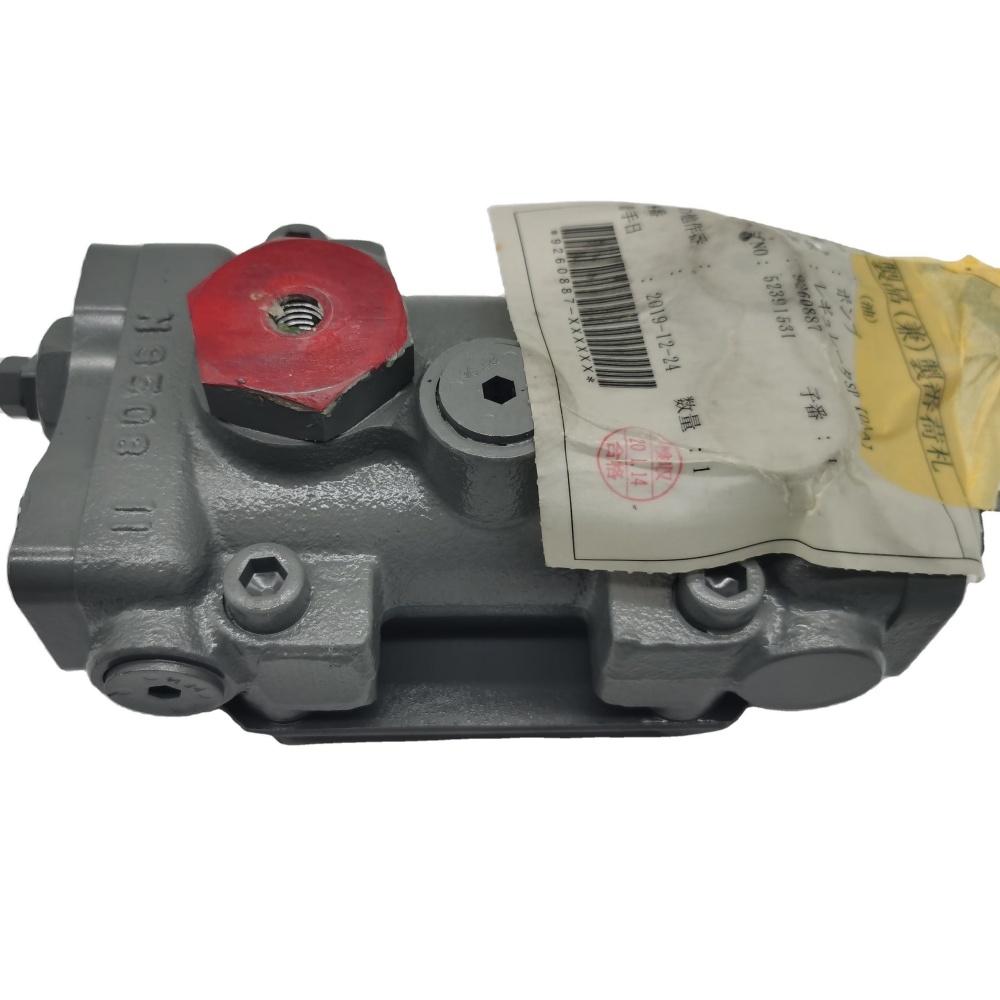
The catalog includes a Hitachi 9260887 / 9253685 regulator listing and a separate Hitachi 9207292 / YB60000398 regulator listing, both associated in their titles with ZX330-3 or ZX330-5A applications. Similar machine wording does not prove that the controls interchange. Use the regulator product category only to identify enquiry candidates.
Send the machine model and complete serial number, main-pump plate, every regulator label and stamped number, installed orientation and clear photos of all ports. Record connector shape and pin count if the control is electrohydraulic. Include the test results and fault pattern. A related Hitachi main-pump listing shows why the pump assembly identity must accompany the regulator request.
Also state the required commercial scope: new, remanufactured or serviceable used condition; regulator only or regulator with linkage, plugs and solenoid; inspection documentation; packaging protection; and the written fitment basis. Ask the supplier to identify which number on the quotation was matched and which interfaces remain for the workshop to confirm. This keeps a catalog similarity from becoming an unsupported interchange claim.
| RFQ field | Evidence | Why it matters |
|---|---|---|
| Machine identity | Model and full serial plate | Separates production ranges |
| Pump identity | Pump maker, model and all plate numbers | Links the control to the correct pump family |
| Regulator identity | Labels, cast marks and stamped numbers | Supports direct comparison |
| Interfaces | Port map, linkage, connector and mounting photos | Prevents physical and control mismatch |
| Test record | Cold/hot signals and response | Supports the repair decision and root-cause review |
Commission with a signal-to-response record
Correct contamination, inlet, pilot, wiring and valve problems before installation. Keep protective caps fitted until connections are ready. Use the excavator manual for seals, torque, priming, bleeding and any calibration. After start-up, compare neutral and commanded signal pressure, engine response, pump output, temperature, noise and leakage with the pre-repair record. Release the machine only when response is stable in every required mode and the safety controls operate normally.