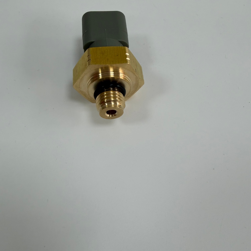
A CAT 336 low-oil-pressure warning does not automatically prove that the T406711 / 320-3060 sensor has failed. The warning may represent real lubrication loss, an electrical circuit problem, a connector fault, a damaged harness, an incorrect sensor, a blocked oil path or an electronic interpretation problem. Running the engine while treating a genuine pressure loss as “just a sensor” can turn a small diagnostic job into major engine damage.
This guide provides a safe evidence sequence for workshops and buyers evaluating a CAT T406711 320-3060 engine oil pressure sensor. It avoids unverified pressure, voltage, torque and compatibility claims. Use the exact CAT service information for the machine serial and engine arrangement.
Separate real low oil pressure from a signal fault
The first decision is whether the engine may have genuinely low oil pressure. Stop operation when the machine instructions require it. Check oil level and obvious leakage using the approved procedure. Review when the warning began, whether it appears cold or hot, at idle or under load, and whether abnormal engine noise or recent lubrication work is involved.
A mechanical pressure test, when specified by the service procedure and performed with the correct equipment, can provide an independent comparison with the electronic reading. Do not improvise an adapter, test point or safe limit. The goal is to compare physical pressure and electronic data under the same controlled condition—not to keep a potentially unlubricated engine running long enough to collect more data.
| Observation | Diagnostic direction |
|---|---|
| Mechanical and electronic readings both indicate low pressure | Investigate the lubrication system before replacing a sensor |
| Mechanical pressure is acceptable but electronic data is implausible | Test sensor supply, ground, signal, connector and harness |
| Reading changes when the harness moves | Inspect terminals, routing, chafing and conductor damage |
| Fault began after engine or harness work | Check part identity, connection, pin condition and installation |
| Evidence is conflicting | Stop and obtain the serial-specific diagnostic procedure |
Identity checks before electrical testing
Record the complete CAT 336 serial/PIN, engine identification, diagnostic codes and the full number on the installed sensor. Photograph the sensor in place, connector face, wire colors, locking features, thread and sealing method. Hongtengda lists T406711 and 320-3060 together for a CAT 336 / C7.1 application, but a web listing does not prove universal interchangeability across every arrangement.
Do not force a connector because it appears similar. Compare keying, pin count, terminal size, lock position and harness strain relief. Confirm the thread and sealing design from verified parts information. A different calibration can share a similar housing, so physical resemblance is insufficient.
Connector and harness inspection
Disconnect power and follow the service instructions before unplugging the sensor. Inspect for oil entry, water, corrosion, spread terminals, bent pins, pushed-back terminals, damaged seals and a broken secondary lock. Check whether the harness is stretched, rubbing, heat damaged or secured in a way that transfers vibration to the connector.
Use terminal test tools that do not enlarge or damage the contacts. Do not insert an oversized probe. If a voltage or resistance check is required, use the correct pinout and meter method from the applicable schematic. A generic three-wire assumption is not a substitute for the exact diagram.
Use scan data as a trend, not a verdict
Capture engine speed, oil temperature, electronic pressure, warning status and operating condition together. A number without its condition has little diagnostic value. Compare key-on/engine-off behavior only when the service procedure calls for it. Observe whether the signal changes smoothly as operating conditions change, becomes fixed, jumps intermittently or moves when the harness is disturbed.
A fault code identifies the circuit or condition the controller detected; it does not always identify the failed component. Supply, ground, signal and connector faults can all make a good sensor appear defective. Likewise, a plausible electronic value does not prove that the lubrication system is healthy unless it has been compared with the required diagnostic evidence.
Replacement and receiving checklist
- Full machine and engine serial information.
- Old sensor numbers and photographs.
- Connector face, keying and terminal count.
- Thread and sealing-interface evidence.
- Relevant codes and scan-data screenshots.
- Mechanical-pressure comparison when safely required.
- Required condition and actual-unit photographs.
- Written confirmation of supplied seal and commercial terms.
The Hongtengda T406711 / 320-3060 product page is a useful inquiry anchor. Verify the decisive details in writing. Caterpillar’s own parts pages warn that machine configuration can affect fitment and recommend serial-aware verification.
Installation without creating a new fault
Inspect the sensor port and connector before installation. Keep dirt out of the lubrication system. Use only the sealing method, tightening specification and tool defined for the exact application. Over-tightening can damage a sensor or housing; under-tightening can leak; an incorrect sealant can contaminate the system or change the electrical ground path on designs that use it.
Route the harness as documented before removal. Confirm adequate slack, correct clips, heat clearance and protection from abrasion. Ensure the connector is fully seated and locked. Clean spilled oil so any new leakage can be traced accurately.
Post-installation acceptance
Before restarting, verify oil level, connector engagement, tools clear and guards in place. Start only according to the machine procedure. Watch for leakage and abnormal sound. Compare electronic data with the pre-repair record under the same safe conditions. Clear codes only as instructed, then confirm whether they return.
If the warning remains, do not continue replacing parts. Return to the evidence tree: physical pressure, circuit integrity, correct part identity and controller inputs. Keep the removed sensor until the repair is validated.
Frequently asked questions
Does a low oil pressure code mean the sensor is bad?
No. It can indicate genuine pressure loss or a circuit problem. Protect the engine first, then follow the serial-specific diagnostic procedure.
Can I test the sensor with a generic resistance value?
Not safely or conclusively unless the exact service information defines that method. Many pressure sensors produce an electronic signal and require correct supply, ground and signal testing.
Are T406711 and 320-3060 guaranteed interchangeable?
Do not treat an online cross-reference as a universal guarantee. Confirm the machine serial, official parts information, old sensor, connector and thread before ordering.
What should I send with an RFQ?
Send the serial/PIN, engine identity, old sensor numbers, connector and thread photographs, relevant codes and test evidence. State the destination and required condition.
Sources and related guidance
Caterpillar explains that an engine-oil-pressure sensor supports lubrication monitoring, while its parts catalog stresses configuration-aware fitment. Use the official Cat sensor description for the general function and the Cat service-manual resources for the applicable procedure. These sources do not confirm that 623-4302 is interchangeable with T406711 / 320-3060.
For broader circuit-testing principles, see the related excavator pressure sensor guide. Send the machine serial, old-sensor evidence and test record through the Hongtengda inquiry page for a written comparison.