An excavator swing motor failure can resemble a problem in the swing gearbox, brake, main control valve, pilot circuit or even the slew bearing. Slow rotation, delayed stopping, drift and abnormal noise describe what the operator feels; they do not identify the failed component. Ordering a motor from the symptom alone can turn one repair into two.
This guide separates the hydraulic motor from the reduction gearbox and surrounding circuit before procurement. It gives workshops a practical evidence sequence for testing, component identification and commissioning. Pressure, flow, case-drain, brake-release and torque limits must always come from the hydraulic schematic and service manual for the exact machine serial number.
Build a symptom map before opening the circuit
Record the complaint in both swing directions with the machine cold and at normal operating temperature. Note start delay, maximum response, stopping distance, rollback on a slope, noise, vibration and leakage. Compare left and right swing only under a controlled procedure with people and obstacles outside the working radius. Save active and stored codes, monitor data and operator observations before disconnecting any line.
Describe when the symptom appears. A motor that is acceptable cold but weak when warm suggests a different investigation from a machine that cannot release its swing brake after startup. A single hard spot at the same upper-structure position can point toward mechanical interference or bearing damage rather than uniform internal motor leakage.
| Observed symptom | Evidence to capture | Systems still in the fault tree |
|---|---|---|
| Slow in both directions | Command, supply pressure/flow, temperature and case-drain result | Pump, control valve, reliefs, motor wear and mechanical drag |
| Slow in one direction | Direction-specific pressure, relief response and valve command | Control spool, crossover relief, port blockage or motor valve block |
| Will not start, then jumps | Pilot command, brake-release pressure and delay time | Pilot circuit, brake piston, valve element or gearbox resistance |
| Excessive coast or drift | Stopping distance, slope condition and holding test | Brake, anti-cavitation/crossover valve, motor leakage or control valve |
| Noise or periodic knock | Position, direction, speed and oil/debris inspection | Motor, reduction gears, output pinion, bearing or slew ring |
Separate the hydraulic motor from the swing gearbox
The swing motor converts hydraulic flow into rotation. The reduction gearbox changes speed and torque before the output pinion drives the slew ring. The two sections may be supplied separately or as an assembly, but oil can remain divided between the hydraulic motor case and the gear compartment. Identify fill, level and drain points before assuming that oil found at one plug came from the other section.
Inspect the mounting interface and surrounding area before cleaning everything. Hydraulic oil around a hose, valve block or motor shaft area differs from gear oil escaping at a gearbox seal. Photograph the leak path, then clean and recheck under the approved procedure. Inspect the gearbox oil for level, condition and metal while keeping the sample tied to the correct compartment.
Caterpillar’s equipment-fluid guidance treats swing-drive oil as a separate service check and directs owners back to the operation and maintenance manual. That example shows why the machine-specific manual, not a generic quantity from another excavator, controls gearbox service.
Test command, brake release and hydraulic supply first
Use the hydraulic schematic to follow the operator command from pilot or electronic input to the main control valve, swing ports, brake-release circuit and return. Confirm that the motor is being asked to move before judging its response. Check whether another function changes the symptom, which may reveal shared pump or flow-priority behavior.
A spring-applied, hydraulically released swing brake can keep the machine stationary even when the motor receives flow. Verify release pressure and timing at the specified test point. Do not defeat the brake or apply unverified external pressure. If the brake remains applied, continued commanding can create heat and damage while making the motor appear weak.
Direction-specific relief and make-up valves can also change acceleration and stopping. Record test-point identity, oil temperature, engine speed and control position with every reading. A pressure number without those conditions cannot be reconciled with the manual.
| Test layer | Question answered | What it prevents |
|---|---|---|
| Command and interlocks | Was swing movement actually requested and permitted? | Replacing hardware when the command is blocked |
| Main-valve delivery | Does the correct port receive supply and return flow? | Condemning the motor for an upstream spool or pump fault |
| Brake release | Does the brake receive and retain the specified release signal? | Operating against an applied brake |
| Crossover/make-up function | Are acceleration, deceleration and anti-cavitation paths working? | Misreading a valve-block fault as motor wear |
| Mechanical drag | Is gearbox or slew resistance affecting both directions? | Installing a new motor onto a damaged drive train |
Use case-drain evidence within the correct procedure
Case-drain flow can help identify internal motor leakage, but only when the manufacturer provides the test method and limit. Hose routing, backpressure, oil viscosity, temperature, speed and load affect the result. Measure at the specified condition with a safe collection or flow-measurement arrangement; do not cap a case drain or route it through an improvised restriction.
Parker’s hydraulic motor catalog shows that case-drain selection and routing vary with motor orientation and that a motor case must contain the specified fluid before startup. The values in that catalog apply to its named motor families, not automatically to an excavator swing motor. The transferable lesson is to verify drain routing, backpressure and prefill requirements for the exact unit.
Danfoss’s axial-piston motor service manual organizes sluggish operation around system checks as well as motor condition. Use that diagnostic logic without importing its test limits. If the swing motor sheds debris or oil shows contamination, investigate the circuit and filters before installing a replacement.
Prepare an interface-based swing motor RFQ
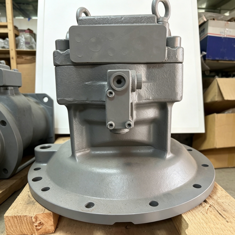
Record the excavator make, full model, serial number and any configuration suffix. Photograph the installed motor from all sides before removing hoses. Tag every port and line, then capture the nameplate, casting numbers, valve block, mounting flange, output interface, overall height and surrounding clearance. State whether the requested scope is a hydraulic motor, reduction gearbox or complete swing drive.
The Hongtengda catalog contains distinct enquiry candidates. A Hitachi ZAX270-3 / ZAX280 swing motor listing names M5X180CHB-10A and 4621174. Another Hitachi EX300-5 motor listing names the 4371768 / M2X210CHB family, while the CAT 305.5E2 / 306E2 listing shows a different compact-machine assembly. The Hitachi rotary category is a catalog entry point, not an interchange chart.
| RFQ field | Buyer sends | Supplier confirms |
|---|---|---|
| Machine identity | Model, serial plate and configuration | Serial-range fitment basis |
| Unit identity | All nameplate, casting and stamped numbers | Quoted motor and manufacturer code |
| Hydraulic interface | Tagged port map, hose ends and valve-block photos | Port functions, threads and supplied plugs or seals |
| Mechanical interface | Flange, pilot, bolt pattern and output details | Comparable drawing or annotated measurements |
| Supply scope | Motor, gearbox or complete drive required | Included brake, valves, gearbox and accessories |
| Failure evidence | Codes, pressure/flow findings, oil and debris record | Cleaning or commissioning requirements |
Commission with a direction-and-temperature release record
Before startup, follow the supplied and machine-specific instructions for cleanliness, fluid, case filling and gearbox oil. Confirm that every line is on its mapped port and that the motor and gearbox mounting faces are seated correctly. Start at the specified low-risk condition and keep people outside the swing radius.
Record left and right response cold, during warm-up and at normal operating temperature. Check brake release, stopping behavior, leakage, noise and relevant pressures without exceeding the prescribed test. Reinspect fluid levels and filters after the interval required by the service procedure. The HSE’s high-pressure fluid guidance warns against searching for leaks with bare hands and stresses pressure release and correct replacement components.
A complete handover identifies the failed subsystem, the evidence that excluded the gearbox and upstream circuit, the installed part, cleaning actions and the final left/right results. That record protects the replacement motor from an unresolved brake, contamination or gearbox problem and gives the buyer a defensible purchasing history.