A shuttle valve chooses between two hydraulic signals and sends the selected pressure to another control. On an excavator, that signal may influence pump control, brake release, travel or implement logic. When a shuttle element sticks, leaks internally or receives a blocked signal, the resulting symptom can look like a pump, pilot valve or main control valve fault. This guide explains how to approach excavator shuttle valve failure as a signal-routing problem.
Understand what the signal valve is selecting
A basic shuttle valve has two inlets and one selected outlet. Pressure at either inlet shifts a ball or spool so the output receives the appropriate signal while the other side is isolated. A multi-port excavator signal valve can combine several such functions in one block. Danfoss describes a shuttle valve as an automatic diverter for hydraulic fluid in a closed circuit in its shuttle valve technical sheet.
The first diagnostic task is to identify what each port does on the exact machine schematic. Do not infer port function from physical position or hose size. Tag the hose at both ends and mark the command associated with it. If a signal is absent at the inlet, the shuttle valve cannot create it; the fault must be traced upstream.
| Symptom pattern | Signal-valve possibility | Other likely area |
|---|---|---|
| One direction or function fails | One inlet blocked or not selected | Upstream pilot valve, hose or command |
| Two functions influence each other | Internal cross-leak or spool not sealing | Incorrect hose routing or main-valve leakage |
| Brake release delayed | Selected signal restricted | Brake piston, orifice, supply or return |
| Fault changes after warm-up | Clearance-related internal leakage | Oil viscosity or another hot-leak path |
Make a port-and-command map before testing
Lower the attachment, isolate the machine and release stored pressure according to the service manual. The HSE’s hydraulic safety guidance warns against hand-checking leaks and highlights stored-pressure hazards. Clean the valve and connections before fitting gauges. Cap every opened line immediately.
Copy the valve symbol from the machine schematic and create a simple table for inlet A, inlet B and selected outlet. For a multi-port block, use the manufacturer’s port names. Record which lever, pedal or machine condition should energize each source. This map prevents a valid upstream signal from being mistaken for the selected output.
Compare both inlet signals with the outlet
Use approved gauges and test points. Record oil temperature, engine speed, safety-lever position and command. Measure the first inlet, second inlet and selected outlet under neutral and each relevant command. A good upstream signal with no corresponding output supports investigation inside the shuttle path. Low pressure at both inlet and outlet points upstream.
A shuttle is also used in circuits that sense the higher work-port pressure to release a brake or pilot another valve. Danfoss illustrates this function in its motor-mount hydraulic circuit information. Use that diagram to understand signal logic only; its pressure values and timing are not specifications for the Hitachi valve.
| Test state | Inlet A | Inlet B | Selected outlet |
|---|---|---|---|
| Neutral | Record | Record | Record stability |
| Command A | Expected signal | Compare/isolate | Should follow correct source per schematic |
| Command B | Compare/isolate | Expected signal | Should transfer without abnormal delay |
| Hot repeat | Record change | Record change | Look for temperature-dependent leakage |
Separate blockage, leakage and routing errors
A blocked hose, crushed tube or contaminated orifice can stop a valid signal before it reaches the valve. A misrouted hose after earlier repairs can produce logical symptoms that no replacement valve will correct. Inspect line tags against the schematic, not against memory. Check for bent fittings, seal fragments and debris at controlled disassembly points.
If the element does not shift freely or cannot isolate the lower-pressure side, internal wear or contamination may be present. Danfoss’s H1B motor information shows how a shuttle spool responds to pressure difference in a loop-flushing circuit. The application differs, but the principle reinforces why both sides and the outlet must be measured. Never polish, drill or substitute springs without manufacturer-approved repair data.
Observe timing as well as peak pressure. A restriction may eventually reach the expected reading but do so too slowly for the commanded function. Record how the outlet rises, stabilizes and returns when each input is applied and released. If the machine’s procedure allows it, repeat the comparison at the valve inlet and at the downstream device. The point where the response changes narrows the fault to a hose, fitting, valve passage or receiving component.
Contamination findings should change the repair scope. A particle that holds the shuttle off its seat may have traveled through other pilot components. Photograph debris, retain a representative sample and inspect the approved filters. Replacing the block without correcting the source, cleaning affected lines and confirming oil condition can expose the replacement to the same failure.
This video explicitly shows Hitachi ZX470 excavator pilot-control hoses and shuttle-valve routing. It provides component context; confirm every connection with the schematic for the serial number being repaired.
Identify the replacement by the complete valve block
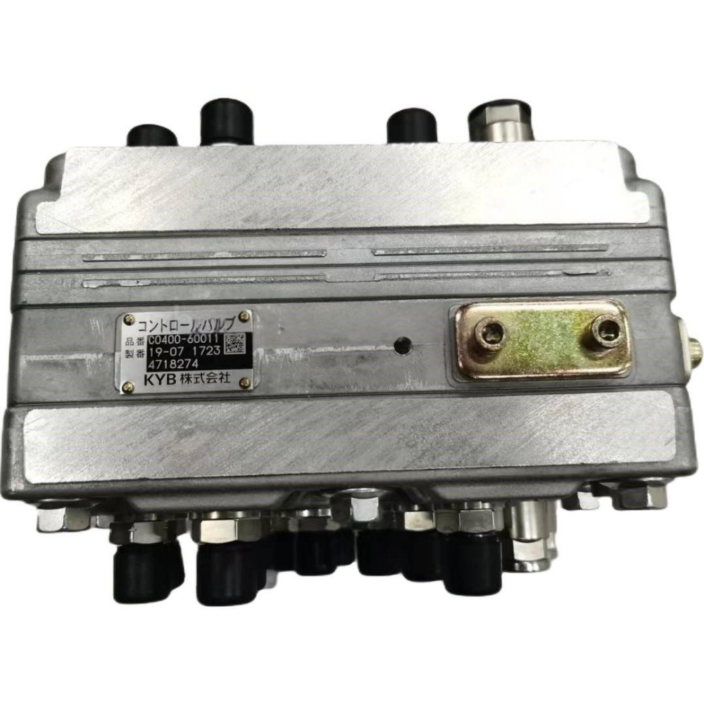
Hongtengda lists a Hitachi 4718274 shuttle signal valve and another 4718274 / YA00000543 signal-valve listing. Shared numbers make them enquiry candidates, but do not prove that every serial range, port fitting or supplied accessory is identical. The Hitachi signal control valve category helps locate both records.
Send the machine model, complete serial number, valve plate, all stamped and cast numbers, installed orientation and a photo of every face. Create a tagged port map showing where each hose goes. Record fitting type, connector details if present and whether brackets or sensors are included. Add the test table so the supplier can see why replacement is being considered. Use the contact page to request a written comparison.
Request confirmation of the supplied scope, port protection and inspection condition. If the old block includes adapters, check valves or special fittings, state whether they will be transferred. Do not assume a photographed plug is included or that an adapter can be moved without changing sealing geometry. A written list of included parts makes receiving inspection possible.
| RFQ item | Required evidence | Mismatch prevented |
|---|---|---|
| Machine identity | Model and full serial plate | Production-range error |
| Valve identity | Plate, casting and stamped numbers | Wrong internal configuration |
| Port map | Tagged photos of every hose and face | Port count and routing error |
| Mounting | Bracket, bolt pattern and orientation | Installation conflict |
| Diagnostic record | Both inlets and output under each command | Unnecessary replacement |
Release the repair with an A-B-output record
Correct contaminated oil, damaged hoses and upstream command faults before fitting the valve. Keep ports capped until each clean connection is ready. Follow the machine manual for seals, torque and bleeding. After installation, repeat the same inlet and outlet tests cold and at stable operating temperature. Confirm that each command transfers cleanly, unrelated functions stay isolated, the machine returns to neutral correctly and no external leakage is present.
Finish by checking the actual working functions that depend on the selected signal, including their complete release and neutral behavior. Record operator control, inlet A, inlet B, selected output and resulting machine action on one line for each state. This A-B-output record provides a clear baseline if a later complaint appears.