An excavator temperature display that reads cold, hot or erratic does not automatically prove that the coolant-temperature sensor has failed. The same symptom can come from a connector, harness, ground, controller, gauge or a real cooling-system problem. This guide organizes excavator coolant temperature sensor testing before replacement and builds the evidence needed for a precise parts enquiry.
Separate a false signal from real overheating
Stop work safely if the machine shows an overheat warning, steam, coolant loss, abnormal odor or reduced power. Do not continue loading the engine merely to see whether the indication changes. With the system safe, record the displayed temperature, warning state, coolant level, ambient condition, engine load and how quickly the reading moved.
Caterpillar’s excavator maintenance checklist ties cooling performance to coolant level, hoses and airflow. Verify the physical system before treating an electrical signal as false. Compare the monitor value with an approved independent temperature measurement at the manual-specified location.
| Signal behavior | Possible electrical cause | Physical condition to rule out |
|---|---|---|
| Maximum hot immediately | Shorted signal or sensor | Actual hot engine before restart |
| Minimum cold after warm-up | Open circuit or lost supply/ground | Thermostat or circulation issue |
| Reading jumps with vibration | Loose terminal or broken conductor | Rapid coolant loss or air pocket |
| Stable but inaccurate reading | Wrong sensor curve or drift | Measurement-location difference |
Identify the circuit before using a meter
Obtain the wiring diagram for the exact machine serial number. Determine whether the component is a one-wire sender, two-wire thermistor, switch or another design. Identify the controller or gauge receiving the signal and any shared reference or ground. Wire color and connector shape alone are not enough to establish terminal function.
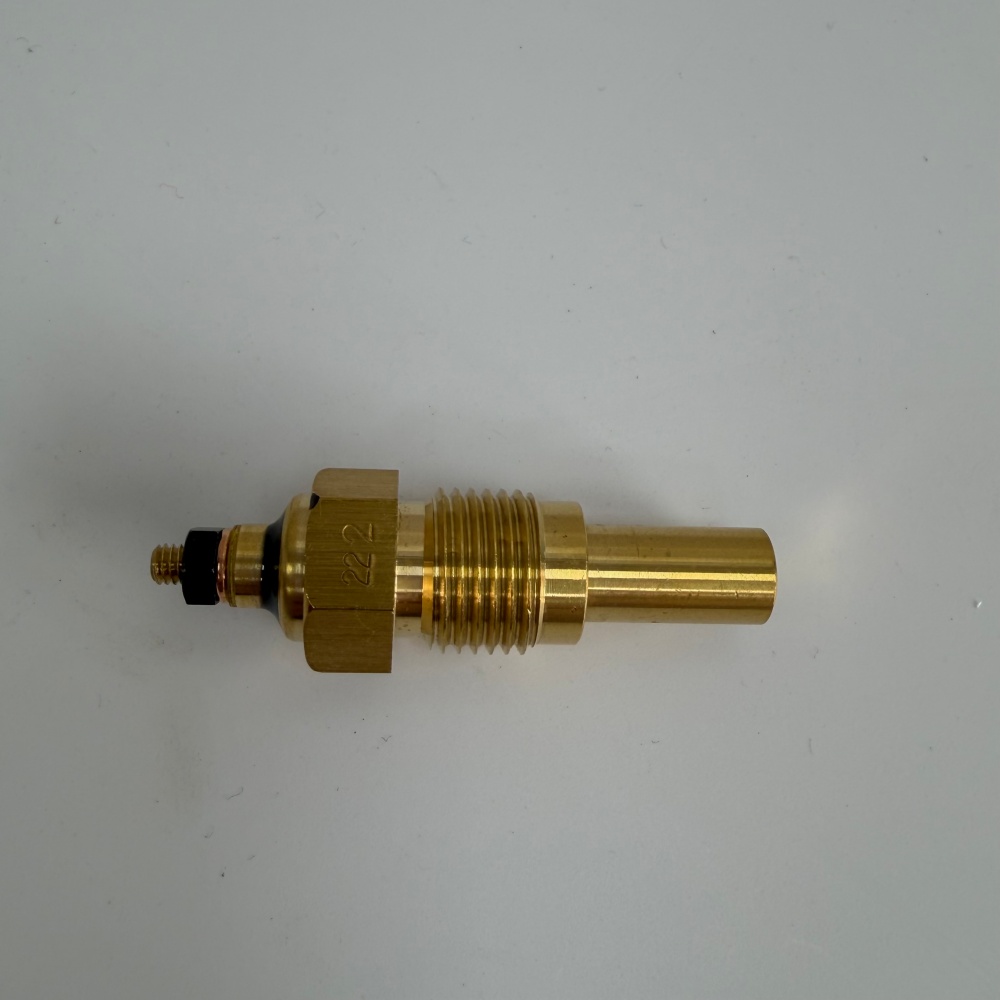
Hongtengda lists a Hitachi coolant temperature sensor associated with 4436537. Treat it as an enquiry candidate. The catalog title includes dimensions and commercial claims, but this diagnostic guide does not adopt those values as fitment or performance proof.
Inspect the connector and harness under safe conditions
Park, lower the attachment, stop the engine and isolate power as directed. Let the cooling system cool before working near the sensor. Inspect for coolant in the connector, corrosion, backed-out terminals, damaged seals, oil-soaked insulation and harness contact with hot or vibrating parts. Support the loom before disconnecting it.
TE’s automotive terminal information shows that retention and sealing are part of terminal performance. Use the specified release and test tools. Oversized meter probes can spread a terminal and create an intermittent fault after testing.
| Inspection point | Evidence | Fault separated |
|---|---|---|
| Sensor body | Leakage, corrosion and impact | Mechanical damage versus signal fault |
| Connector seal | Moisture path and latch condition | Contamination-driven intermittence |
| Terminal position | Retention and contact condition | Open or high-resistance connection |
| Harness route | Heat, rub, pinch and vibration points | Conductor damage |
| Shared circuits | Other sensor readings and codes | Reference or controller problem |
Test the sensor across known temperatures
If the wiring diagram identifies a resistive sensor, disconnect and measure only by the machine procedure. Record sensor temperature and resistance together; a single room-temperature reading cannot confirm the complete response curve. Fluke’s temperature-sensor testing guide recommends comparing resistance with the applicable data at known temperatures. Use Hitachi’s curve, not a generic table.
Where in-circuit voltage testing is specified, verify reference, ground and signal at defined operating states. Avoid shorting adjacent terminals or applying external voltage. Compare the value at the sensor connector and receiving controller to isolate harness loss. If the service tool displays a plausible temperature while the monitor is wrong, continue into display or communication diagnosis rather than replacing the sensor.
Temperature sensors can change gradually with heat. Record several stabilized points during a controlled warm-up if the manual permits. Fluke’s multi-point sensor testing guidance supports comparing a sensor with a known reference, while the sensor type and expected curve remain machine-specific.
Match mechanical and electrical interfaces in the RFQ
Use the excavator sensor category to locate enquiry candidates, then send the machine and engine serial plates, old sensor number, thread and sealing-seat photographs, connector view, terminal count, installed location and test results. State whether a sealing washer, connector pigtail or installation hardware is required.
A related Hitachi expansion tank listing belongs to the cooling system but is not a sensor substitute. Include tank or coolant-level evidence only when it supports the fault diagnosis. Similar brass bodies can contain different sensing curves, switch points, threads or sealing methods.
| RFQ field | Evidence to send | Supplier confirmation |
|---|---|---|
| Machine and engine | Complete serial plates | Applicable production range |
| Old sensor | All numbers and full-body photos | Direct identity basis |
| Mechanical interface | Thread, seat, probe and clearance | Installation compatibility |
| Electrical interface | Connector, terminal count and circuit type | Signal compatibility |
| Test evidence | Known temperature and measured response | Replacement decision context |
Install and commission against an independent reference
Use the specified drain level, seal, thread treatment and torque. Do not use sealing material that can insulate a ground path unless the manual requires it. Reconnect the harness with its seal and support intact, refill or bleed the cooling system by the approved procedure and correct any real overheating cause.
During controlled warm-up, compare the service-tool value, monitor indication and independent reference at recorded points. Check for leakage and stable connector operation after vibration and full cool-down. Use the Hongtengda contact page to submit the identification package. Clear codes only as directed and release the machine when the temperature signal and cooling system both behave correctly.