A blank, flickering or unresponsive monitor does not prove that the display itself has failed. An excavator monitor depends on power, ground, communication, sensors and stable connectors, while a machine fault can also cause the panel to display valid warnings. This guide structures excavator monitor panel failure diagnosis so workshops can preserve fault evidence, test the circuit and prepare a defensible replacement request.
Classify the screen behavior before disconnecting power
Record the complaint with ignition state, engine condition and ambient temperature. Photograph the screen and capture any code, symbol, backlight behavior or restart pattern. Note whether gauges and warnings update, buttons respond, the buzzer sounds and the problem changes with vibration. Ask whether the battery, alternator, controller, radio or harness was recently serviced.
Caterpillar describes an excavator monitor as an operator interface for machine information and settings in its mini excavator advanced monitor overview. That helps define the panel’s role, but its Cat functions and architecture do not establish Hitachi wiring or diagnosis.
| Observed state | Possible circuit area | Evidence to collect |
|---|---|---|
| Completely blank | Supply, ground, wake-up input or internal power section | Backlight, fuse state and connector voltage under load |
| Backlight but no data | Communication, controller state or display electronics | Codes, network test and other module behavior |
| Intermittent restart | Voltage drop, loose terminal or internal fault | Event conditions and supply trace |
| One warning or gauge wrong | Sensor, wiring, controller data or valid machine condition | Independent parameter and service-tool comparison |
Preserve codes and configuration before removal
Do not unplug the panel as the first test. Photograph every screen and use the correct service tool to save active and logged codes where supported. Record language, hours, machine settings and any attachment or operator configuration that may require transfer. A power reset may clear intermittent evidence or make a communication problem temporarily disappear.
Caterpillar’s excavator monitor control guide shows that current monitors can store operator input settings. The features vary by model, but the lesson is useful: document configuration before disconnecting a display. Follow the exact Hitachi service procedure for data backup, replacement and calibration.
Test power and ground under the fault condition
Obtain the wiring diagram for the full machine serial number. Identify constant supply, key-switched supply, ground, wake-up, illumination and communication terminals. Inspect the correct fuses and shared relays. Measure voltage at the monitor connector with the circuit connected when the procedure allows; an open-circuit reading can look normal through a high-resistance connection.
Use the specified ground point and compare supply voltage with battery voltage while the monitor is starting. A voltage-drop test can expose corrosion or loose terminals that an ohmmeter misses. Fluke’s 88V multimeter manual provides general measurement and safety methods, but the machine schematic controls pins, acceptable values and whether back-probing is allowed.
Repeat measurements while the reported symptom is present. If the display fails only during cranking, at high electrical load or after warming, capture the supply and ground behavior during that event. Check shared circuits because a failing relay or ground splice may affect several devices. Avoid jumper wires or substitute feeds unless the service procedure specifically authorizes them; an incorrect feed can damage the panel or another controller and can bypass circuit protection.
| Check | Method boundary | Fault separated |
|---|---|---|
| Battery condition | Approved battery and charging-system test | System-wide low or unstable voltage |
| Monitor supply | Correct pin, state and loaded reading | Fuse, relay, switch or feed resistance |
| Monitor ground | Voltage drop during panel operation | Loose, corroded or shared ground fault |
| Wake-up/illumination | Schematic-defined input behavior | Command fault mistaken for dead panel |
| Communication | Approved service tool and network procedure | Harness/module network fault |
Inspect connectors and separate data faults
Isolate power by the machine procedure before terminal inspection. Look for poor latch engagement, backed-out terminals, spread contacts, bent pins, corrosion, moisture, fretting and harness strain. Do not force a test probe into a terminal. TE’s automotive terminal guidance illustrates that terminals are engineered systems with retention and sealing features; any repair must preserve the specified contact and seal.
If supply and ground remain correct during the complaint, test network wiring and controller communication by the service manual. A panel showing one implausible value may be faithfully displaying bad sensor or controller data. Compare the monitor reading with service-tool data and an independent test where the manual permits. Replacing the display before this comparison can leave the original fault untouched.
Use a substitution test only with a unit whose compatibility and programming state are confirmed. A borrowed monitor that powers up but cannot communicate may simply belong to a different hardware or software variant. Likewise, a working display can appear faulty when the network is being held down by another module. Record which modules communicate with the service tool, which codes are active and whether the network fault remains when the approved isolation sequence is followed.
The video below is explicitly about a Hitachi Dash-6 excavator monitor panel and shows its operating context. Use it for component recognition only. It does not provide the pinout, coding or fitment proof for the ZX200-3 / ZX330-3 / ZX470-3 panel discussed here.
Build a panel RFQ from hardware and software identity
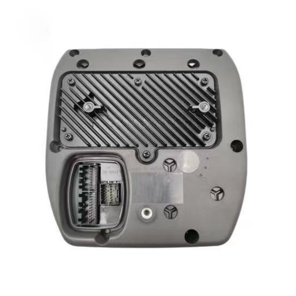
The catalog includes a Hitachi ZX200-3 / ZX330-3 / ZX470-3 monitor panel listing associated with 4652262 and 4631127. A related ZAX200-5G switch-panel listing is a different operator-control part and should not be treated as a substitute. Use the switch and instrument category to identify enquiry candidates only.
Send the machine model and full serial number, original panel label, every part and software number, front and rear photographs, connector faces, mounting pattern and screen behavior. State whether configuration, hour data, language, immobilizer or other programming support may be required. Ask the supplier which identifier was matched and whether the offered unit is new, remanufactured or used.
| RFQ field | Evidence | Why it matters |
|---|---|---|
| Machine identity | Model and complete serial plate | Separates production and electrical variants |
| Panel identity | Full label, part numbers and software marks | Supports hardware and version comparison |
| Interfaces | Connector faces, pin count and mounting photos | Prevents physical or harness mismatch |
| Fault evidence | Photos, codes and voltage/network results | Supports the replacement decision |
| Commissioning need | Configuration and calibration requirements | Defines supply and support scope |
Commission the display against saved evidence
Correct supply, ground, connector, network and sensor faults before fitting a replacement. Keep protective covers installed until connection. Follow the machine procedure for static protection, mounting, power-up, programming and calibration. Restore only documented settings and confirm that the displayed hours and configuration follow the authorized process.
After installation, test start-up, backlight, buttons, buzzer, warnings, gauges, service-menu communication and required machine modes. Compare live values and codes with the pre-repair record. Use the Hongtengda contact page to send the identification package when requesting a written comparison. Release the excavator only when the panel, underlying machine inputs and safety warnings all respond correctly.
Finish with a controlled key-off and restart, then inspect the connector and mounting after the cab has been operated through its normal vibration and temperature range. Save the original panel label, diagnostic report and configuration record with the work order. If a fault returns, this package makes it possible to compare supply, communication and display behavior without repeating the first diagnosis from memory.