An excavator that will not respond correctly to its engine-speed knob may have a failed dial, but it may also have a lost supply, poor ground, damaged signal wire, connector problem or controller input fault. Replacing the panel before measuring the circuit can waste the part and preserve the downtime. This excavator throttle dial failure guide organizes a state-based test and a B2B identification package.
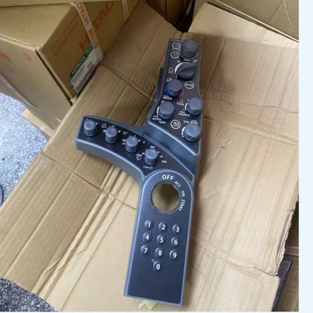
Turn the complaint into dial positions and responses
Record whether engine speed is fixed, jumps, changes only through part of the dial, reacts in the wrong direction or becomes intermittent with vibration. Note work mode, automatic idle state, warning codes, engine temperature and whether another engine-speed command works. Video the panel and tachometer while moving the control slowly through its full travel without operating the machine unsafely.
Caterpillar advises checking loose controls, broken switches and monitor damage as part of excavator maintenance in its mini excavator maintenance guidance. That supports a physical inspection, while the exact Hitachi logic and test values must come from its serial-specific manual.
| Behavior | Possible area | Evidence needed |
|---|---|---|
| No response at any position | Supply, ground, signal, controller state or dial | Codes and connector measurements |
| Dead section in travel | Worn resistive track or intermittent terminal | Smooth sweep test and harness movement comparison |
| Speed changes without dial movement | Loose connection, damaged harness or controller input | Event trace and connector inspection |
| Dial value changes but engine does not | Command path beyond the input | Service-tool command and engine-control diagnosis |
Identify the complete control assembly
Photograph the machine serial plate, panel face, rear label, connector and mounting points. Record every part number and revision. Determine whether the dial is supplied separately or only with a larger switch-panel assembly. Count connector positions without assuming that wire colors define pin function. A visually similar knob can use a different electrical range, direction, detent or connector.
The catalog contains a Hitachi ZX180W-7 throttle dial assembly listing associated with YA00049351. Treat it as an enquiry candidate whose title still requires serial, panel and connector confirmation. Use the switch panel and instrument category to compare other control layouts, not to infer interchangeability.
Inspect the dial, connector and harness safely
Park the machine, lower the attachment, stop the engine and isolate electrical power by the service procedure. The HSE’s work-equipment maintenance guidance supports safe isolation and competent maintenance. Check for a cracked knob, impact damage, liquid entry, loose mounting and restricted movement. At the rear, inspect latch engagement, seals, terminal position, corrosion, fretting and wire strain. Support the harness so panel removal does not pull on the terminals.
TE’s automotive terminal information shows the importance of contact retention and sealed connector construction. Use the approved extraction and inspection tools. Do not insert oversized probes, pierce insulation without an authorized repair method or bend a terminal to create temporary contact.
| Physical checkpoint | Accept by | Fault prevented |
|---|---|---|
| Knob and shaft | Smooth travel and secure attachment | Mechanical slip or blocked movement |
| Panel housing | No crack, liquid path or deformation | Contamination and misalignment |
| Connector latch and seal | Fully retained, clean and undamaged | Intermittent supply or signal |
| Terminal contact | Specified tension and position | High resistance or open circuit |
| Harness routing | No rub, stretch, pinch or unsupported mass | Repeat conductor failure |
Test the input as a continuous signal
Use the serial-specific wiring diagram to identify the dial circuit. Depending on design, the control may be a potentiometer, switched network or encoded input. Confirm supply and ground first, then measure the signal only by the manufacturer-approved method. Compare the value at several marked dial positions and move the dial slowly in both directions while watching for dropouts or jumps.
Fluke’s 97/AUTO manual section on variable-position sensors explains that a potentiometer produces a changing voltage for an electronic control unit and recommends observing the full sweep. This is a general principle. Do not import its example resistance range, pin arrangement or voltage into an excavator circuit.
Mark a repeatable set of positions on a photograph instead of writing “low,” “middle” and “high.” Record the value while turning upward and again while turning downward. A difference between directions can reveal mechanical play or an unstable track. Perform an authorized light harness movement test while watching the signal; if the value changes without dial movement, isolate the connector and loom before ordering the control. Keep meter leads secured so they cannot short adjacent pins.
The video below is explicitly about troubleshooting a throttle-dial harness on a Hitachi Zaxis 225USR-3 excavator. It is relevant to separating the input from the loom, but its connector access and readings must not be treated as ZX180W-7 specifications.
Separate dial output from controller and engine response
If the dial output changes smoothly at the panel, repeat the approved measurement at the receiving controller or compare the service-tool parameter. A good signal at the dial but a missing value at the controller points toward the harness or connectors. A correct controller input with no engine response moves diagnosis beyond the dial toward operating mode, interlocks, controller output, engine actuator or engine fault.
An engine stop limit-switch listing represents another input in the broader control system, but it performs a different function and is not a throttle-dial substitute. Check related inputs only where the wiring diagram or fault logic connects them to the complaint.
Automatic idle can confuse the comparison because the controller may intentionally reduce speed when the machine is inactive. Follow the manual’s conditions for disabling, commanding or observing that function. Note whether engine speed follows the dial while a work function is active and whether the service-tool target agrees with actual speed. This separates an accepted operator command from a downstream actuator or engine-control problem.
| Test location | Result pattern | Next decision |
|---|---|---|
| Dial supply and ground | Missing or unstable | Repair shared feed or ground before condemning dial |
| Dial output | Jump, dropout or dead band | Confirm connector, then assess dial replacement |
| Controller connector | Signal lost between ends | Isolate harness and terminal fault |
| Service-tool input | Tracks dial correctly | Continue into control logic and engine response |
| Commanded engine response | Incorrect despite valid input | Use engine-control diagnostic procedure |
Quote and commission with a position record
Send the supplier the full machine serial number, panel and dial numbers, connector photographs, mounting layout and the test results at marked positions. State whether a dial, a harness section or the complete panel assembly is required. Ask whether the offered part includes the knob, electronics, overlay, seals and mounting hardware, and which identifier supports fitment.
Use the Hongtengda contact page to send this evidence for written comparison. Before fitting a replacement, correct liquid entry, terminal damage or harness strain. Follow the machine manual for power isolation, installation and any calibration. After power-up, confirm a smooth displayed input and stable engine response across every documented position, then test automatic idle and required work modes. Record the installed number, position readings and final fault-code state for handover.
Retest after the cab and hydraulic system reach normal working condition because heat and vibration can expose an intermittent connection that passes a stationary check. Confirm that nearby panel functions were not disturbed during access. Keep the old unit until the repair record and supplier return requirements are complete, with its connector protected from dirt and static damage.