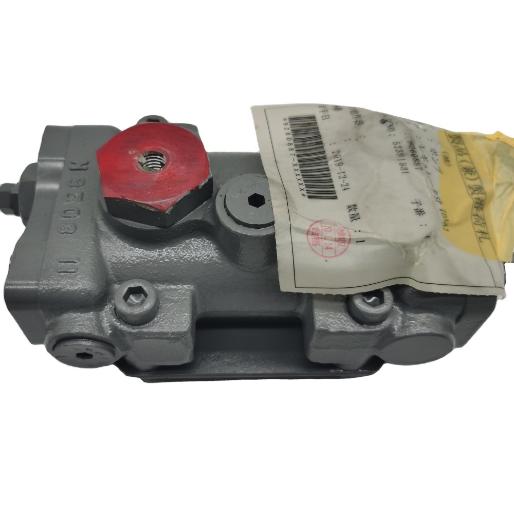
An excavator main pump regulator diagnosis must explain why the pump changes displacement incorrectly before anyone adjusts or replaces the regulator. The regulator is part of a control loop. It reacts to one or more hydraulic signals, spring settings, pilot pressures, load-sensing pressures, power-control pressures, or electronic commands and moves the pump’s servo mechanism. The servo mechanism changes swash-plate angle, which changes displacement and therefore available flow at a given shaft speed.
When this loop fails, the excavator may be slow, the engine may lug, one pump may behave differently from the other, standby losses may rise, oil may overheat, pressure may build late, or several functions may interact abnormally. The same complaints can also come from suction restriction, internal pump wear, main-control-valve leakage, blocked signal lines, weak pilot supply, faulty sensors, wiring, engine power loss, or incorrect previous adjustment. A regulator should therefore be diagnosed as part of the complete machine system.
This professional guide gives field technicians, rebuild shops, fleet teams, and B2B buyers a structured path from symptom capture through hydraulic testing, teardown evidence, regulated adjustment, commissioning, and parts identification. It explains general control principles. The machine and pump service manuals control port identity, test conditions, pressure values, flow limits, spool dimensions, spring settings, adjustment direction, locknut torque, cleanliness class, and acceptance criteria.
Understand what a pump regulator controls
A variable-displacement axial-piston pump can change the volume it moves during each shaft revolution. In a swash-plate design, a larger effective swash angle generally produces greater piston stroke and displacement, while a smaller angle destrokes the pump. A servo piston supplies the force needed to move the mechanism against opposing hydraulic and spring forces. The regulator meters control oil to create the required servo response.
Different excavator pumps use different combinations of control functions. A pressure compensator can reduce displacement when pressure reaches its setting. A load-sensing control can respond to the difference between pump pressure and a downstream load signal. A torque or power control can reduce displacement as pressure increases so the hydraulic system does not demand more engine torque than the power train can provide. Electronic proportional controls can add commands or corrections. Multi-pump systems may also share or cross-reference signals.
The Parker Hydraulic Pump Basics document describes pressure-compensator, load-sense, torque-limiter, and electronic-displacement control as distinct functions. This helps explain why a visual match does not establish regulator calibration or interchangeability. A housing may contain different spools, sleeves, springs, orifices, plugs, and settings for a specific pump and machine.
Translate the operator complaint into test conditions
Record the exact condition before connecting gauges. Is the machine slow cold, hot, or at all temperatures? Do boom, arm, bucket, swing, and travel respond equally? Does combining two functions improve or worsen the symptom? Does the engine speed drop sharply under one function, under all relief tests, or even at neutral? Did the problem begin after pump work, hose replacement, controller programming, contamination, or engine repair?
Save diagnostic codes and live data before clearing them. Record engine speed, commanded mode, hydraulic-oil temperature, pilot pressure, relevant sensor values, and pump-control current when the system provides them. Note attachments, boom position, track position, and any auxiliary circuit configuration. Repeatable test conditions matter because oil viscosity, engine speed, load, and control mode can alter results.
| Complaint pattern | Possible directions | Evidence needed |
|---|---|---|
| All functions slow, engine stable | Low pump displacement, pilot/control issue, suction restriction | Both pump flows, servo/control pressures, inlet condition |
| One pump group weak | Individual regulator, pump, signal path, or valve section | Pump mapping, comparative flow and pressure tests |
| Engine lugs under hydraulic demand | Excess displacement, power control error, engine power loss | Engine performance plus pump torque-control data |
| Hot performance deteriorates | Internal leakage, viscosity-sensitive clearance, heat load | Cold/hot flow, case drain, temperature and leakage comparison |
| Functions interact or surge | Unstable signal, sticking spool, air, sensor or control issue | Synchronized pressure, current and displacement evidence |
Map the hydraulic and electronic control paths
Obtain the correct hydraulic schematic and identify pump outputs, pilot supply, regulator ports, load-sense or negative-control paths, torque-control signals, servo-piston passages, drain paths, sensors, and solenoids. Trace each physical hose or passage on the machine. A hose connected to the wrong regulator port after repair can create a convincing “bad regulator” symptom.
If the pump is electronically influenced, obtain the electrical schematic too. Identify power, ground, command, feedback, and controller pins. The controller may calculate pump command from engine speed, throttle request, pressure sensors, angle feedback, temperature, work mode, and fault strategy. A substitute signal or fixed current applied without the official test plan can overload the engine or pump.
Create a port map before disconnecting anything. Photograph labels, paint marks, hose tags, adapters, orifices, and plug positions. Mark the front and rear regulator or pump number when two similar units are installed. Never infer port function from its location alone.
Establish safe, clean test conditions
High-pressure hydraulic fluid can penetrate skin, hot oil can burn, and raised equipment can move unexpectedly. Follow the manufacturer’s lockout, warm-up, support, pressure-release, gauge-rating, hose-restraint, and test-area procedures. Use remote readings and guards where required. Seek immediate medical care for suspected injection injury.
Use calibrated gauges, flow meters, temperature sensors, tachometers, breakout leads, and diagnostic software with adequate ratings. Clean test ports before connection and use compatible caps. Keep all hoses and cables clear of fans, couplings, exhaust, tracks, and articulation. Confirm emergency shutdown responsibilities before loading the hydraulic system.
Warm the machine using the specified procedure. Record oil temperature at each result. A pressure or flow number without temperature, engine speed, command state, and test point is incomplete. Do not hold a circuit against relief longer than the service instruction permits.
Prove basic machine health before blaming the regulator
Verify engine condition and rated-speed response. A fuel, air, turbocharger, derate, or engine-control problem can make a correctly regulated pump appear over-stroked. Confirm batteries and controller supplies, active engine codes, throttle command, and actual speed. Compare no-load and hydraulic-load behavior by the official procedure.
Inspect hydraulic level, oil condition, filters, suction hoses, tank breather, cooling package, and evidence of aeration. A restricted inlet can reduce flow and damage the pump. Air can make control pressure unstable. Contaminated oil can stick regulator spools and damage servo surfaces. A blocked case drain can raise case pressure and affect pump life.
Check pilot pressure and any control supply feeding the regulator. A regulator cannot position its servo correctly without the specified control energy and drain path. Inspect small signal hoses for kinks, crushed sections, internal delamination, swapped connections, blocked fittings, and debris. Small orifices are especially vulnerable to contamination and unauthorized drilling.
Measure pressure, flow, case drain, and speed together
Pressure alone cannot prove displacement. A worn pump may reach pressure at low flow, while a healthy pump may be destroked by a control signal. A flow test without engine speed and pressure also lacks context. Collect synchronized pump outlet pressure, pump flow, engine speed, oil temperature, case-drain flow, and the relevant regulator signal or command.
Use the machine’s pump-to-function map. On a twin-pump excavator, test each pump independently where the manual allows, then observe combined functions. Compare front and rear results at the same temperature and engine speed. If the symptom changes sides when a permitted control signal is exchanged, that evidence can narrow the fault; do not swap hoses unless the manufacturer’s diagnostic procedure explicitly instructs it.
Case-drain measurement helps evaluate internal leakage, but the correct port, hose routing, backpressure, oil temperature, pressure load, and duration are essential. A high reading may indicate rotating-group or servo leakage rather than a regulator alone. A low reading does not prove the regulator responds correctly.
| Measurement | Primary question | Common interpretation error |
|---|---|---|
| Pump outlet pressure | Can the system build pressure under the defined load? | Assuming pressure proves adequate flow |
| Flow at controlled pressure | How much displacement is produced under the test state? | Ignoring engine speed and temperature |
| Regulator signal pressure | What command reaches the control? | Using the wrong port or generic target |
| Servo pressure or position | Does the control create movement? | Condemning the regulator when the servo binds |
| Case drain | Is internal leakage excessive under defined conditions? | Blaming regulator settings for rotating-group wear |
| Engine speed | Does pump demand match available engine power? | Adjusting the pump to hide an engine problem |
Distinguish regulator faults from pump wear
A regulator can stick, leak internally, lose spring force, suffer spool or sleeve wear, contain a blocked orifice, or receive the wrong external signal. The pump can separately suffer worn pistons, cylinder block, valve plate, bearings, swash components, servo piston, or housing. The two fault groups influence each other.
If control pressures and commands change correctly but pump displacement responds slowly or not at all, investigate servo movement and internal pump condition. If the pump can produce flow when directly tested by an approved procedure but does not respond to its normal control signal, the regulator or signal path becomes more likely. If case drain is excessive and hot flow collapses, replacing only the regulator may not restore performance.
Contamination can damage both. A particle may hold a small control spool off its seat while larger debris scores the rotating group. Before approving a regulator-only repair, inspect filters and oil, review pump history, and decide whether the system requires broader contamination control.
Analyze pressure-compensator and load-sense behavior
In a pressure-compensated system, the control reduces pump displacement as outlet pressure approaches its target. In a load-sensing system, a pressure difference across the metering element influences pump displacement. The Parker PD pump technical information explains how a generic load-sense and pressure-limiter control adjusts output to demand. Excavator circuits may use different names and arrangements, so only the machine schematic determines the real signal path.
When standby pressure is abnormal, inspect the load-sense or control signal and its drain or bleed path before turning an adjustment. A trapped high signal can keep the pump stroked. A lost signal can keep it destroked. Internal leakage in the main valve, a blocked fitting, or a wrong hose connection can create the same effect as a sticking regulator spool.
Record pressure on both sides of the relevant control relationship when the manual requires a differential. Two absolute readings taken at different moments cannot define a dynamic pressure margin. Use matched calibrated channels and a shared time base when transient response matters.
Analyze torque or power-control behavior
Excavator pump controls often limit hydraulic input torque so the engine can maintain usable speed. As outlet pressure rises, permitted displacement may decrease. On a twin-pump system, the control may account for pressures from both pumps. Springs, pistons, pilot signals, and electronic trim can shape the response.
An engine-lug complaint is not permission to back out a regulator screw. First verify engine output, mode selection, pressure-sensor data, pump commands, and both pump loads. If only one pump is incorrectly over-stroked, a shared engine symptom may hide the side responsible. If the engine is weak, reducing pump displacement may make the machine appear acceptable while sacrificing performance and leaving the engine fault unrepaired.
Plot pump pressure against flow or displacement through the defined test points. Compare the curve with the serial-specific standard rather than a single relief reading. A shifted curve, unstable transition, or unequal twin-pump response can reveal a control problem that a static check misses.
Inspect electronic commands and feedback
Some controls use proportional solenoids or electronic displacement systems. Bosch Rexroth describes pump systems that control swivel angle, pressure, and power, illustrating how feedback and command signals can be integrated. This is a general example, not proof that a particular Hitachi regulator uses the same architecture.
Use the correct schematic to test supply, ground, command current, signal voltage, and continuity. Measure under load whenever the procedure specifies it. An unplugged circuit can show normal voltage but fail when the coil operates. Inspect connector locks, terminal tension, seals, corrosion, oil intrusion, chafing, shielding, and prior splices.
Compare commanded and actual values through the fault event. If the controller commands destroke but the pump remains at high displacement, investigate the actuator, regulator, servo, and wiring. If the command itself is wrong, investigate the inputs and software strategy. Never apply direct battery voltage or a guessed duty cycle to a proportional control.
Use response testing to find sticking and hysteresis
A regulator may reach the correct endpoint slowly, overshoot, oscillate, or respond differently as the command rises and falls. Step-response testing with synchronized pressure, flow, command, and engine-speed data can reveal this behavior. Use only service-manual test steps and safe loading.
Repeat the test cold and at specified operating temperature. Viscosity can change leakage and spool response. Compare increasing and decreasing commands to look for excessive hysteresis. Tap tests or external force are not valid diagnostics unless the manufacturer specifies them; impact can damage precision components and create misleading temporary changes.
The Danfoss Series 45 service manual shows how pump controls contain defined spools, springs, pressure paths, and adjustment procedures. It also demonstrates why a generic setting cannot be transferred to another pump family.
Decide whether field adjustment is justified
Adjustment is justified only after the machine has the correct oil and temperature, engine health is verified, signal paths are correct, gauges and flow meters are calibrated, internal leakage is acceptable, and the exact procedure and target values are available. Preserve the original setting with photographs, exposed-thread measurement, or approved reference marks before changing anything.
Identify every adjustment by the manual. Similar screws may control maximum pressure, standby margin, torque, minimum displacement, or another function. Adjustment direction can differ. A small change can have a large effect. Loosen and tighten locknuts with the specified support and torque so the screw does not rotate unintentionally.
Change one variable at a time and record the amount. Repeat the complete relevant test after each change. Confirm interaction with other control functions. If the target cannot be reached within the permitted range, stop and investigate wear, wrong parts, blocked passages, signal errors, or pump damage. Do not continue turning the screw beyond the allowed position.
| Adjustment gate | Required evidence |
|---|---|
| Correct component | Pump tag, regulator marking, machine serial and parts information agree |
| Healthy supply | Engine, pilot pressure, inlet, drain, oil and filters verified |
| Valid instruments | Rated, calibrated and installed at specified points |
| Original baseline | Pressure, flow, temperature, speed, signals and settings recorded |
| Official limits | Serial-specific test condition, target, tolerance and torque available |
| Controlled change | One adjustment, recorded increment, complete retest |
Remove and inspect the regulator without losing evidence
If field testing supports removal, clean the pump exterior and surrounding area first. Release pressure and prevent unintended movement. Mark every hose and connector. Photograph the regulator orientation, plugs, shims, exposed adjustments, fittings, and external damage. Cap openings immediately with clean compatible caps.
Regulator bodies contain precision spools, sleeves, springs, seats, shims, pistons, and small orifices. Work in a controlled clean area with a compartmented tray. Follow the disassembly sequence. Do not polish a spool, enlarge an orifice, stretch a spring, or mix components from similar-looking regulators. Matched spools and sleeves may need to remain together.
Inspect for scoring, varnish, corrosion, impact, broken springs, damaged seats, blocked passages, seal extrusion, fretting, and unauthorized prior work. Measure only with the methods and limits provided by the pump documentation. Record where contamination was found because its location may explain the control failure.
Evaluate regulator parts and pump interfaces together
Check the regulator mounting face, locating features, passages, O-ring grooves, plugs, and mating pump surface. A damaged seal between control passages can cross-connect signals. A blocked pump-body drilling can make a good regulator appear defective. Verify the servo piston and linkage move as specified.
If the pump is opened, inspect the swash mechanism, servo bore, bearings, rotating group, valve plate, and case-drain paths. The regulator cannot compensate for excessive mechanical friction or internal leakage. Conversely, a sticking regulator can command damaging operating states, so the root-cause sequence matters.
Use a decision table rather than replacing every visible part without analysis.
| Evidence | Likely repair scope | Additional proof |
|---|---|---|
| Clean regulator, wrong external signal | Repair hose, valve, sensor, wiring, or command source | Signal restored and response verified |
| Scored spool with system debris | Regulator plus contamination-source and system cleanup | Filter/oil analysis and affected-component inspection |
| Correct control pressure, servo binds | Pump servo or internal mechanical repair | Servo and swash mechanism measurements |
| High case drain and hot flow loss | Full pump condition assessment | Rotating-group and housing inspection |
| Settings disturbed but parts acceptable | Controlled bench or machine calibration | Recorded full-range response and lock verification |
Control cleanliness during rebuild
Clean the work area, tools, test oil, plugs, and containers to the documented standard. Keep new seals packaged until installation. Use lint-free materials and compatible cleaning fluid. Verify every drilled passage and calibrated orifice without altering its size. Dry components by the approved method.
Install spools, springs, shims, pistons, plugs, and seals in the correct locations and orientations. Apply specified lubricant. Confirm free movement where the procedure calls for it. Use calibrated torque tools and the correct tightening sequence. Record part numbers and any selective components.
If the regulator is tested on a bench, document oil type and temperature, drive speed, control pressures, flow points, adjustment values, leakage, response, and final seals or paint marks. A statement that the regulator “was tested” is not enough for an audit or warranty review.
Identify the correct replacement regulator
Hongtengda lists a regulator associated with references 9260887 and 9253685 and another regulator associated with 9207292 and YB60000398. Both listings mention Hitachi ZX330-family applications, but this does not prove interchangeability. Similar castings can contain different internal configurations or calibration.
Send the complete machine model and serial number, hydraulic-pump manufacturer and full tag, pump assembly number, regulator marking, and the old component photographs. Include every side, port, plug, adjustment, connector, and mounting face. Record dimensions and port arrangement only as supporting evidence; do not replace official identification with measurements alone.
State whether the machine has a mechanical, hydraulic, electro-hydraulic, or mixed control arrangement according to the schematic. Provide controller codes, pressure and flow results, and the failure history. Ask the supplier to confirm the identification basis, supplied configuration, seals, calibration state, test report, preservation, packaging, warranty, and installation requirements.
Install and commission in controlled stages
Before installation, correct the root cause and complete required system cleaning. Confirm the pump and mating surfaces are clean and undamaged. Install the correct seals, fittings, orifices, and fasteners. Reconnect every hose and connector according to the port map. Fill or prime the pump and control passages by the official procedure; dry starting can damage the pump quickly.
Begin with pre-start electrical and hydraulic checks. Then crank, start, and warm the machine as specified. Observe noise, leaks, case pressure, pilot supply, control signals, and engine speed. Increase hydraulic demand in planned steps. Compare both pumps and stop for abnormal heat, noise, pressure, flow, case drain, or engine loading.
Perform the complete calibration or acceptance test, not only the original failing function. Check standby behavior, controlled flow points, pressure limitation, power-control curve, combined-function response, electronic feedback, and hot operation. Recheck locks, seals, and leaks after shutdown if the manual requires it.
| Commissioning stage | Record | Release decision |
|---|---|---|
| Pre-start | Identification, cleanliness, oil, hoses, connectors, priming | Correct deficiencies before rotation |
| Initial start | Noise, leakage, pilot/control pressure, engine speed | Stop or continue to warm-up |
| Warm neutral | Standby behavior, temperatures, control signals | Confirm stable baseline |
| Staged functions | Pressure, flow, engine response, front/rear pump balance | Identify control mismatch |
| Full specified test | Curves, limits, case drain, hot performance | Accept, readjust, or reopen |
| Post-test | Leaks, codes, locks, oil/filter checks | Release with monitoring plan |
Create an auditable regulator decision record
The final file should contain the original complaint, machine and pump identity, schematic revision, codes, baseline conditions, instrument details, pressure-flow-speed-temperature records, signal traces, teardown photographs, contamination evidence, dimensional findings, repair scope, adjustment log, and final commissioning results.
State the failure mechanism supported by the evidence. For example, a blocked signal orifice caused delayed destroking; contaminated oil scored the control spool; a cross-connected hose sent the wrong pressure; or rotating-group leakage prevented the commanded response. If the exact cause remains uncertain, document the leading explanation and the controls used to reduce recurrence.
The site’s hydraulic pump specification guide helps organize pump identification, while the pump seal-kit rebuild checklist addresses sealing scope. For written regulator comparison, send the full evidence package through the Hongtengda parts inquiry page. Identification and diagnostic proof should come before adjustment, price, or delivery decisions.