

Description
Product Video
1. The “Core Role” – The Only Feedback for Your Pump’s Brain (PVC)
On Hitachi EX and ZX series excavators (EX120/200/220-3, ZAX330/450/470/650, etc.), the main pump’s displacement is not fixed—it changes continuously to match the load. The brain (the PVC controller) sends an instruction to increase or decrease pump flow, but how does it know if the instruction was actually followed? Through this angle sensor.
| Component | Role in the System |
|---|---|
| PVC (controller) | The brain. Calculates the target swashplate angle based on engine load, joystick signals, and system pressure. |
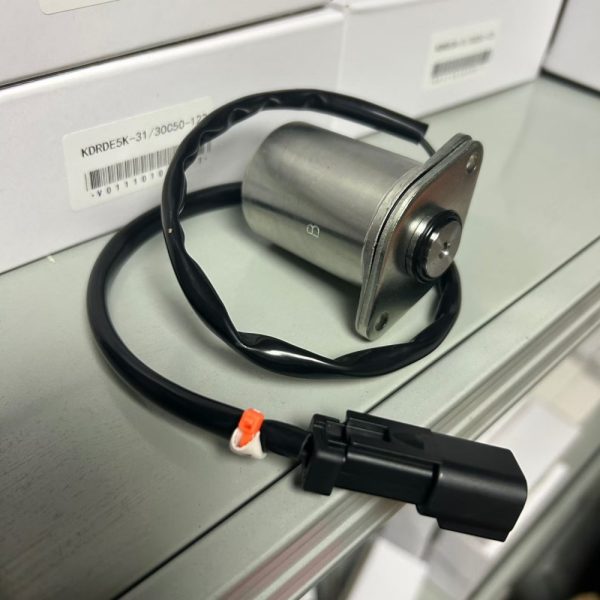
| High-speed solenoid valves | The muscles. Receive pulse signals from the PVC and control the servo piston to move the swashplate. |
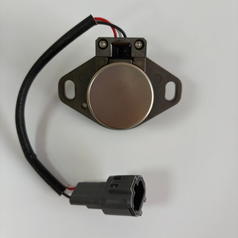
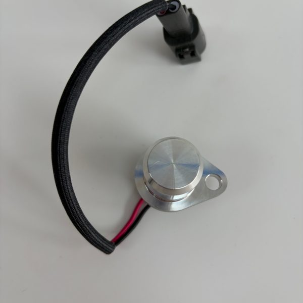
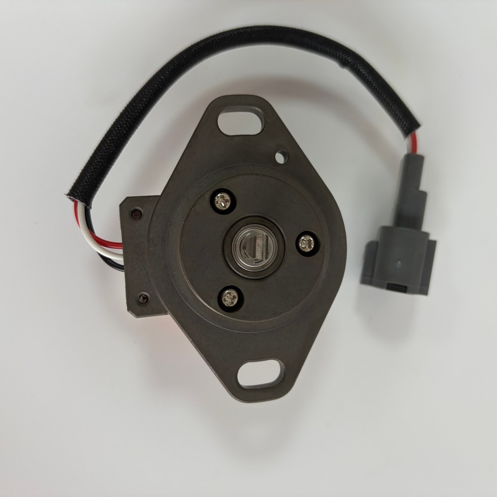
| Angle sensor (4444902 / 9102385 / 4716888) | The only eye. Mechanically linked to the swashplate, it measures the actual angle and sends a voltage signal (0.25-4.75V) back to the PVC. |
Without this feedback, the PVC is flying blind. It will keep issuing commands without knowing if the pump is actually responding [11†L8-L11].
2. How It Works – The RVDT Principle
This sensor is an RVDT (Rotary Variable Differential Transformer). Unlike a simple potentiometer (which wears out), an RVDT has no contact between moving parts, making it extremely durable.
| Parameter | Specification |
|---|---|
| Swashplate angle range | 2° – 24° |
| Corresponding voltage output | 0.25V – 4.75V (linear) |
| Sensing principle | Non-contact magnetic induction |
| Supply voltage | 5V DC (regulated by PVC) |
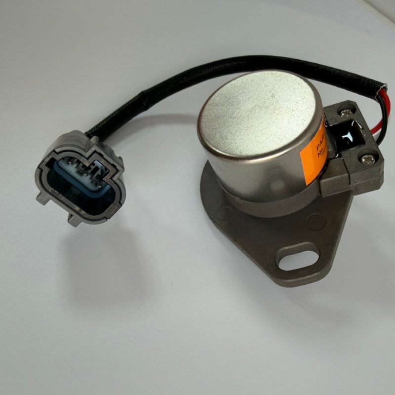
| Connector | 3-pin (Vcc, Ground, Signal) |
As the swashplate rotates, the sensor’s internal core moves, changing the magnetic coupling between primary and secondary coils. The output voltage changes proportionally to the angle [11†L9-L11].
3. The “Crash Course” – What Happens When the Eye Lies
A faulty angle sensor rarely fails completely. More often, it drifts, sending an incorrect voltage to the PVC. The consequences can be catastrophic.
| Failure Mode | What the Sensor Does | What the PVC Thinks | What the Machine Does |
|---|---|---|---|
| Sensor drift (output too high) | Sends 3.0V (actual angle 15°) but should be 1.5V (actual angle 5°) | PVC thinks pump is flowing less than actual | PVC commands HIGHER flow → Engine overload → Engine stalls under load |
| Sensor drift (output too low) | Sends 1.0V but should be 3.5V | PVC thinks pump is flowing more than actual | PVC commands LOWER flow → Machine lacks power, slow digging |
| Sensor stuck (mechanically) | Output stays at 2.5V regardless of angle | PVC thinks pump is at mid-angle | PVC keeps sending conflicting commands → Hunting, surging, erratic behavior |
| Sensor disconnected | No signal (0V or open circuit) | PVC enters “limp home” mode | Fixed reduced pump flow – machine operates at 50-60% power |
The most dangerous failure: A sensor that reads lower than actual [11†L9-L14]. Example: actual angle 20° (high flow) but sensor outputs 2.0V (mid flow). The PVC thinks flow is too low, so it commands even higher flow. The engine becomes overloaded and may stall violently during digging.
4. Real Case – The “Engine Stalls When Digging” Nightmare
A customer’s EX200-3 worked fine at idle but would stall every time the bucket entered a hard bank. They replaced fuel filters, injectors, the lift pump, and even had the injection pump tested. Nothing fixed it.
The problem was an angle sensor that had drifted by 2.0V. At full load, the actual swashplate angle was 22°, but the sensor told the PVC it was only 14°. The PVC responded by opening the solenoid valves for maximum flow. The engine was asked to deliver 130% of its rated power and stalled.
One sensor replacement fixed it. Cost: under $100. Total prior misdiagnosis costs: over $1,200.
5. Installation Critical – The 180° Rule
The angle sensor is not “plug and play” in the sense that you can mount it arbitrarily. It has a mechanical orientation requirement that, if ignored, will cause exactly the failures described above.
| Rule | Requirement | Consequence of Ignoring |
|---|---|---|
| Index mark alignment | The arrow or dot on the sensor body must be aligned 180° opposite to the linkage pin when the swashplate is at minimum angle | The sensor will read backwards. When actual angle increases, output voltage decreases. The PVC will respond opposite to what is needed. |
Installation steps:
-
Ensure the engine is off and hydraulic pressure is relieved.
-
Remove the old sensor. Note the orientation of the linkage arm.
-
Before installing the new sensor, verify that the linkage arm (connected to the swashplate) is at the minimum angle position (engine off, no pilot pressure).
-
Install the new sensor so that its index mark is 180° opposite the linkage pin.
-
Torque the mounting bolts to 8-10 Nm – the sensor body is plastic. Overtightening will crack it.
-
Reconnect the 3-pin harness. Apply dielectric grease to prevent corrosion.
-
Start the engine and verify that the angle reading on the diagnostic tool changes smoothly as you operate the joysticks.
A sensor installed backwards will not be detected by the PVC’s self-diagnostics. The machine will run, but poorly.
6. Is This Sensor a Problem for Your Machine?
Check these three things to determine if your angle sensor is healthy:
| Check | Method | Healthy Result |
|---|---|---|
| 1. Voltage at minimum angle (engine off) | Back-probe the signal wire (pin 3) with a multimeter. Ground to pin 2. | 0.5V – 0.7V |
| 2. Voltage at maximum angle (full joystick, stall load) | Measure while digging (or safely stall the bucket against a solid object) | 4.0V – 4.5V |
| 3. Smooth transition | Slowly move joystick from neutral to full | Voltage rises smoothly, no jumps or dropouts |
If the voltage is stuck, jumps erratically, or is out of range, replace the sensor.
7. Genuine vs. “Compatible” – What You’re Actually Paying For
| Feature | Genuine Hitachi (Japan) | “Compatible” Aftermarket |
|---|---|---|
| Linearity error | <±1% | Often ±3-5% (or unspecified) |
| Temperature stability | Tested from -20°C to +100°C | Unknown – often drifts when hot |
| Internal connector pins | Gold-plated | Tin-plated – corrodes faster |
| Mean time between failures | 8,000 – 12,000 hours | 2,000 – 4,000 hours (if lucky) |
| Warranty support | 6 months (manufacturing defects) | Varies – often no support |
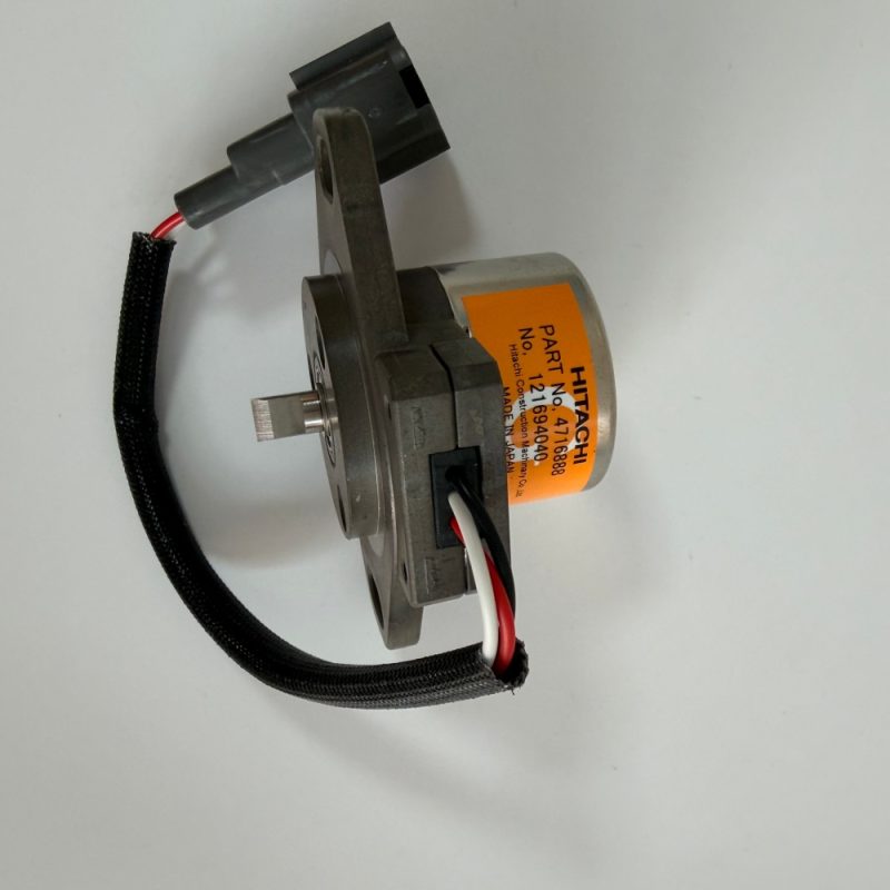
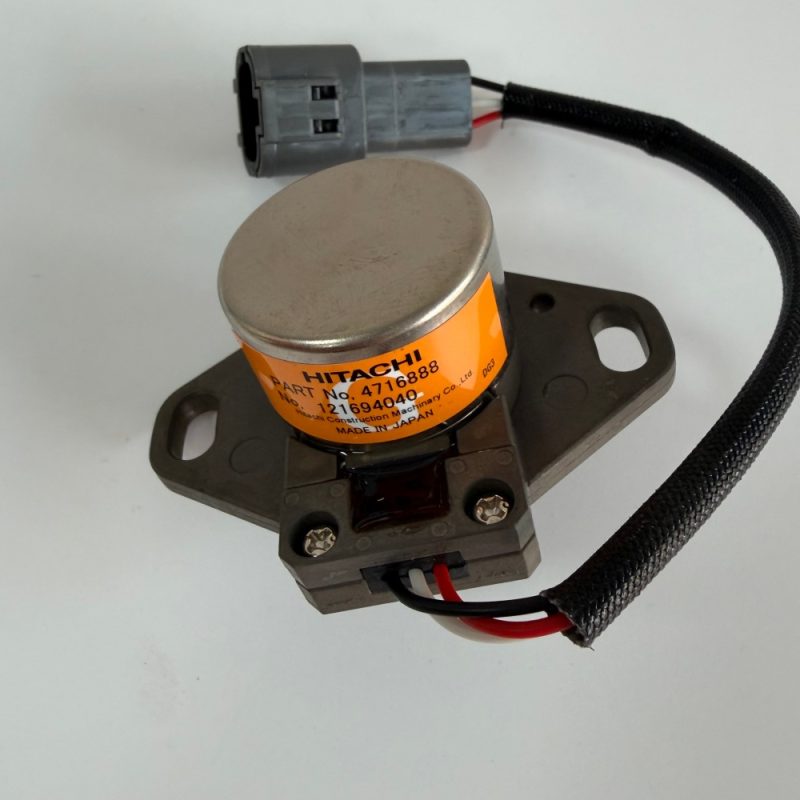
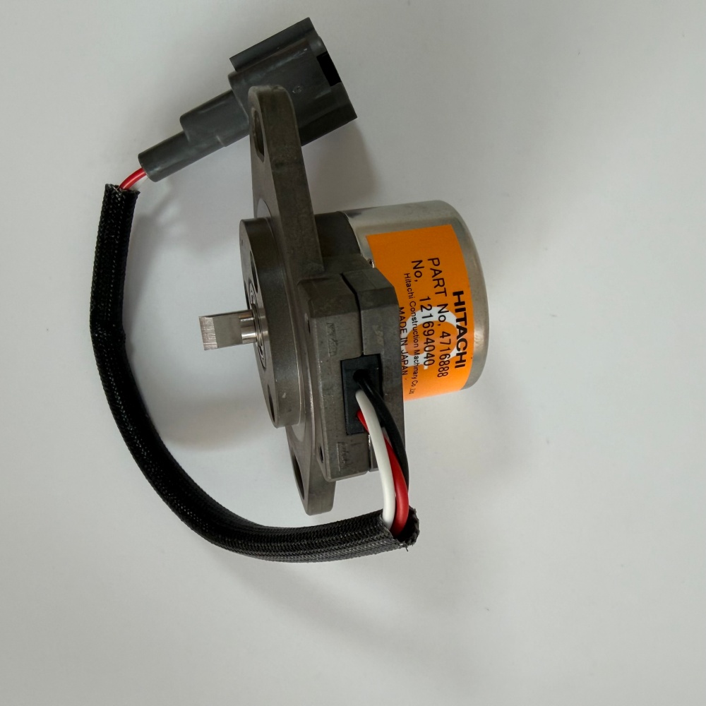
Our sensor: Genuine Japanese (4444902 / 9102385 / 4716888, depending on your machine generation). We do not sell “compatible” versions of this critical feedback device.
8. Product Contents – What You Receive
| Item | Included |
|---|---|
| Angle sensor (RVDT type) | ✅ (Japan) |
| Linkage arm pin (if applicable) | Check – some models reuse the old pin |
| Mounting bolts (2 pcs) | ✅ |
| Protective caps | ✅ |
| Paper box with part label | ✅ |
| Installation orientation guide | ✅ (printed card) |
Not included: Harness (part of machine). Replacement pigtail available upon request if your connector is damaged.
9. Ordering & Delivery
| Item | Detail |
|---|---|
| Part numbers (interchangeable) | 4444902, 9102385, 4716888 |
| MOQ | 1 piece |
| Lead time | 6–8 working days |
| Packaging | Paper box + bubble wrap in carton |
| Payment | T/T, XTransfer, PayPal, Western Union |
| Supply capacity | 300 pcs/month (genuine, limited) |
| Warranty | 6 months (manufacturing defects – electrical drift, mechanical seizure) |
10. Before You Order – Verification
Send us:
-
Machine serial number (EX120-3-xxxx, EX200-3-xxxx, ZAX330-xxxx, etc.)
-
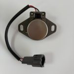
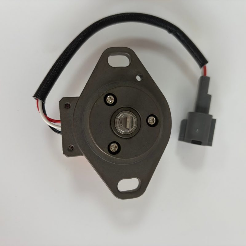
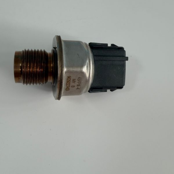
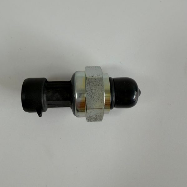
One clear photo of your old sensor (showing the connector and any visible part number)