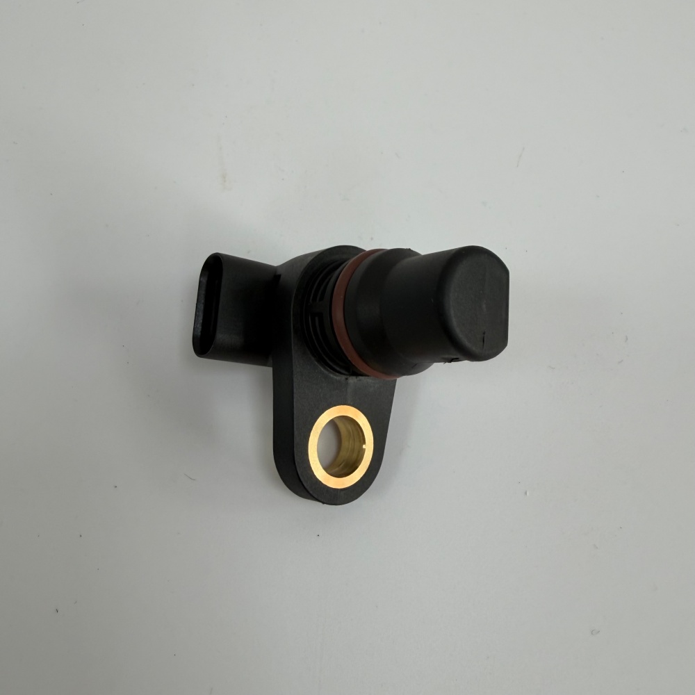
Excavator crankshaft position sensor testing should prove the entire speed-and-timing signal path, not just replace a sensor after a no-start code. The engine controller uses a crank or speed signal to recognize rotation and establish timing. A damaged target wheel, excessive air gap, contaminated tip, poor mounting, failed power or ground, harness defect, connector problem, or controller input can produce symptoms that look like a failed sensor.
Typical complaints include cranking with no start, intermittent shutdown, extended starting, unstable speed display, fault codes, or an engine that starts cold but stops when hot. These symptoms are not exclusive to the crankshaft sensor. Low cranking speed, weak batteries, fuel-pressure faults, missing camshaft synchronization, power-supply problems, and mechanical timing faults can create similar results.
Identify the circuit before testing
Obtain the correct machine and engine electrical diagrams. Identify sensor type, terminal assignments, supply voltage, ground path, signal wire, target location, specified gap, expected cranking-speed data, and controller connector pins. A two-wire variable-reluctance sensor and a powered Hall-effect sensor require different tests. Applying an inappropriate resistance or voltage test can mislead the technician or damage the circuit.
The Hongtengda catalog lists a CAT 481-5929-associated crankshaft position sensor. Caterpillar’s official 481-5929 product page identifies it as a speed sensor group and also makes clear that machine configuration affects fitment. Treat the part number as a starting point, then confirm the engine arrangement and serial-specific parts information.
Begin with scan data and cranking condition
Record active and logged diagnostic codes before clearing anything. During cranking, watch engine speed, synchronization status if available, battery voltage, fuel pressure, and relevant enable conditions. If the controller shows a plausible, stable cranking speed, the sensor path may be working even though another input prevents starting. If speed is zero or erratic, continue through the sensor, target, wiring, and controller checks.
Cranking speed must be adequate for a meaningful test. Inspect batteries, cable voltage drop, grounds, starter performance, and engine mechanical drag first. A slow or unstable crank can reduce signal quality and fuel-system performance together.
| Observation | Possible direction | Next evidence |
|---|---|---|
| Zero speed while cranking | No signal, open circuit, power/ground loss, target problem | Power, ground, waveform and target inspection |
| Erratic speed value | Intermittent wiring, gap, damaged target, noise | Wiggle test and synchronized waveform |
| Stable speed but no start | Other enable, fuel, timing, or synchronization fault | Follow engine diagnostic tree |
| Heat-related stall | Temperature-sensitive sensor, connector, harness or controller | Capture data through temperature change |
Inspect the sensor, target, and mounting
Disconnect power as the service procedure requires. Inspect the connector lock, terminal tension, seal, water entry, corrosion, oil contamination, chafing, and previous repairs. Check the harness near clamps, hot surfaces, sharp edges, and vibration points. A wire can remain connected by a few strands and pass an unloaded continuity test while failing in operation.
Remove the sensor only by the approved procedure. Inspect the mounting ear, bore, O-ring, tip, and any captured metal. Examine the target wheel through the available access point for broken, bent, missing, or contaminated features. Verify mounting cleanliness and air gap with the specified method. Do not add washers or alter the tip position to imitate another part.
Test power and ground under load
For a powered sensor, back-probe with suitable adapters and the circuit connected whenever the manual permits. Verify supply voltage and ground quality during cranking, not only with the connector unplugged. A high-resistance connection can display normal voltage on a digital meter without load but collapse when the sensor operates. Measure voltage drop across the ground path and supply path according to the diagram.
Never assume pin identity from connector shape or wire color alone. Production revisions and prior harness repairs can change appearances. Use the serial-specific schematic and connector views. Avoid piercing insulation; use sealed breakout leads and repair any required access by the approved method.
Evaluate the signal with the correct instrument
An oscilloscope provides more evidence than a resistance check. It can show whether the signal switches or alternates, whether amplitude changes with cranking speed, whether teeth or reference gaps repeat correctly, and whether interference or dropouts occur. Capture enough engine revolutions to see a repeating pattern. Record time base, voltage scale, coupling, probe location, battery voltage, and cranking speed.
Compare the signal at the sensor and, when safe and specified, at the controller input. A good sensor waveform that disappears at the controller points toward wiring or connector loss. A poor waveform at the sensor can result from the sensor, target, gap, mounting, speed, or test setup. A perfect-looking waveform still requires comparison with the engine manual because controller thresholds and timing relationships vary.
| Test | What it proves | What it does not prove alone |
|---|---|---|
| Resistance | Limited winding continuity on applicable sensor types | Powered-sensor operation or dynamic signal quality |
| Supply voltage | Voltage exists at the measured point | Loaded circuit integrity or correct pinout |
| Ground voltage drop | Ground path performance under the test load | Target condition or controller recognition |
| Oscilloscope waveform | Dynamic signal shape, repetition and dropouts | Correct mechanical timing without a reference channel |
| Scan-tool speed | Controller receives and interprets a speed value | Cause of a separate no-start condition |
Use cam-and-crank correlation when required
Some engines need both crankshaft and camshaft information for synchronization. If the manual calls for correlation testing, capture both signals on separate channels with a shared time base. A shifted relationship may indicate a target, mounting, wiring, or mechanical timing problem. Do not declare the crank sensor failed merely because synchronization is absent.
Save known-good reference captures from verified machines with the same engine arrangement and software, while still using official limits. Reference waveforms make intermittent faults and target damage much easier to recognize.
Repair the circuit and verify the result
If a harness repair is allowed, use the specified wire size, terminal, crimp, seal, splice location, and routing. Keep the signal circuit away from noise sources as designed. Secure the harness without tension at the sensor. Replace damaged connector housings and terminals instead of forcing loose contacts tighter.
After repair, clear codes only after saving the original record. Cold start, hot run, restart, and load the engine through the conditions that produced the complaint. Monitor engine speed and synchronization, repeat the waveform if needed, and inspect the harness while safely applying a controlled wiggle test. The repair is complete when the symptom does not recur and the signal remains stable.
If the circuit passes but the engine still stops or fails to start, follow the complete engine diagnostic procedure. The site’s excavator wiring harness guide covers connector and harness evidence, while the engine stop switch diagnosis guide addresses another shutdown path.
Send complete data with a sensor RFQ
Provide the machine model and serial number, engine model and arrangement, old sensor part number, connector face photograph, wire count, mounting view, sensor length, and scan codes. Add photographs of the target area when accessible. Ask the supplier to confirm the identification basis and connector, mounting, sensor technology, and included seal.
Do not approve an order from a shared model name or similar plug alone. For a written comparison, send the evidence through the Hongtengda parts inquiry page. Keep the supplier’s confirmation with the test record so installation and warranty decisions remain auditable.