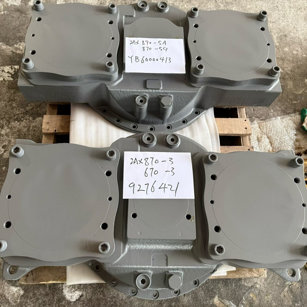
An excavator pump transfer case failure can imitate a hydraulic pump problem, an engine problem, or even a control-system fault. The transfer case sits between engine output and one or more hydraulic pumps. Its job is mechanical: accept torque, divide it through gears and shafts, support those rotating members on bearings, and keep the drive train aligned and lubricated. A defect anywhere in that path can produce noise, heat, metal debris, unstable pump speed, seal leakage, or complete loss of hydraulic power.
The expensive mistake is to replace pumps before proving where the fault begins. A pump with internal damage can load the transfer gear train. A worn coupling can hammer the input. A failed bearing can move a gear out of mesh. Low or contaminated oil can damage several components at once. For that reason, a professional diagnosis must connect the operating symptom to pressure data, speed data, lubricant evidence, vibration location, shaft condition, gear contact, bearing condition, and housing geometry.
This guide gives repair shops, fleet teams, and B2B buyers a disciplined path from the first complaint to a controlled rebuild and commissioning record. It explains general engineering practice. The machine service manual and the exact pump-transfer-case manual remain the authority for oil grade, level procedure, backlash, bearing settings, clearances, torque, lifting, and acceptance limits.
What the pump transfer case does
Large excavators often need substantial hydraulic power for boom, arm, bucket, swing, travel, cooling, and pilot functions. The transfer case creates a compact mechanical junction between the engine and hydraulic pumps. An input flange, shaft, or coupling receives engine torque. A gear set then transmits that torque to output shafts connected to the pumps. Bearings control the shaft positions, the housing preserves center distances, seals retain lubricant, and breathers manage internal pressure.
This arrangement explains why the same symptom can have several causes. If an output bearing develops clearance, gear contact shifts and noise rises under load. If a pump begins to seize, the gear train sees abnormal torsional load. If the input coupling is worn, the case may sound damaged even when its gears remain reusable. If oil level is wrong, heat and foaming can appear before visible tooth failure. Diagnosis should therefore treat the engine coupling, transfer case, pump interfaces, and pumps as one connected drive system.
The Hitachi pump transmission oil information emphasizes lubrication, gear operation, wear protection, and corrosion protection for this type of application. That supports a general point: lubricant is a working component, not merely a consumable. It carries heat, separates surfaces, suspends contaminants, and preserves evidence that can identify the failure mechanism.
Build an evidence chain before disassembly
Start with the operator’s description, but convert it into conditions that can be repeated. Record whether the complaint occurs cold or hot, at idle or high speed, with one hydraulic function or several, during engine acceleration, during pump destroking, or after a particular repair. Note the first date, machine hours, recent oil or pump work, and whether the symptom appeared suddenly or progressed over time.
Inspect the machine before cleaning it. Photograph leaks, breather condition, mounting bolts, coupling guards, hose routing, case damage, and displaced paint around joints. Confirm fluid level by the manufacturer procedure. Draw a clean oil sample and retain the drain oil through a fine screen. Label each sample with oil temperature, machine hours, sampling point, and operating condition. A mixed, unlabeled sample has little diagnostic value.
| Evidence | What to record | What it may indicate |
|---|---|---|
| Noise | Location, frequency, load, speed, temperature | Gear mesh, bearing, coupling, pump pulsation, or resonance |
| Temperature | Comparable points and stabilized operating condition | Friction, preload, low oil, overload, or restricted heat rejection |
| Lubricant | Level, color, odor, foam, water, particle type | Oxidation, aeration, contamination, tooth or bearing damage |
| Vibration | Sensor location, direction, speed and load | Unbalance, looseness, gear mesh, bearing defect, or misalignment |
| Hydraulic behavior | Pump speed, pressure response and affected functions | Pump load, drive interruption, control issue, or multiple-system fault |
Never use a screwdriver or improvised probe near rotating parts. Follow the machine lockout, guarding, lifting, fire, and hot-fluid procedures. If listening or vibration measurements require operation, use approved instruments from a safe location. Large transfer assemblies store considerable mass and may move when mounts or pumps are removed.
Separate transfer-case symptoms from hydraulic pump faults
A noisy pump-transfer area does not prove gear damage. Hydraulic pressure ripple can excite the housing. A pump input bearing can transmit vibration into the case. A deteriorated flexible coupling can knock during speed changes. An engine firing or mount problem can generate a repeating vibration that appears at the transfer housing. The diagnostic question is not “Where do I hear it?” but “Which component creates the energy, and how does the signal change with operating state?”
Compare the mechanical symptom with hydraulic loading. If the noise changes sharply when a particular pump loads, identify the output connected to that pump. If it follows engine speed with the hydraulic system unloaded, inspect the input path, bearings, and gear mesh. If one hydraulic circuit is weak but the corresponding pump shaft turns at the expected speed, investigate that pump and its controls before condemning the transfer case. If several pump outputs become erratic together and input speed is stable, a shared mechanical drive problem deserves attention.
Where the service procedure allows, measure engine speed and each accessible pump or output speed with calibrated equipment. Review hydraulic pressures and control commands using the correct test points. Do not disconnect a pump or operate a partially assembled drive merely to isolate a noise unless the manufacturer explicitly provides that procedure. The safest useful comparison often comes from synchronized speed, pressure, temperature, and vibration measurements during normal tests.
The site’s excavator hydraulic pump specification guide explains the identification data needed when the pump itself becomes a suspect. The related hydraulic pump drive gear inspection guide focuses more narrowly on gear evidence. Use both records with the transfer-case findings so the repair scope addresses the cause rather than only the most damaged part.
Use lubricant and debris as failure evidence
Oil condition can narrow the search before teardown. A low level may point to leakage, a wrong fill procedure, or neglected service. Foamy oil can result from aeration, overfilling, contamination, or return agitation, depending on the design. Dark oil and a burned odor suggest excessive temperature or prolonged oxidation. Milky appearance may indicate water, while visible metallic particles demand controlled inspection.
Separate magnetic from nonmagnetic debris and document size, shape, color, and quantity. Fine ferrous paste on a magnet may differ in significance from fresh flakes or chips. Copper-colored material may come from a cage, thrust surface, or bushing. Seal fragments, paint, and gasket material can also reveal previous work. Laboratory oil analysis can add particle counts, elemental trends, viscosity, water, and oxidation data, but one sample should be interpreted against oil age, top-ups, filtration, and baseline history.
Do not flush away all evidence before the cause is recorded. Conversely, do not treat every particle as proof that every gear must be replaced. The location and morphology matter. A chipped tooth produces a different pattern from broad adhesive wear. A collapsing bearing may send secondary debris through otherwise serviceable gears. The purpose of the evidence chain is to identify the initiating failure and the parts exposed to its debris.
During operation inspection, bearing manufacturers recommend watching noise, vibration, temperature, and lubricant condition. The NSK operation-inspection guidance is useful for these general observations, while the exact excavator manual supplies the machine-specific limits.
Interpret noise, temperature, and vibration carefully
Gear mesh produces characteristic frequencies related to shaft speed and tooth count. Bearings can produce repeating impact patterns related to geometry and speed. Looseness may create harmonics and modulation. These principles make vibration analysis powerful, but a spectrum without a shaft-speed reference, tooth count, sensor orientation, and baseline can be misleading. Collect repeatable data at marked measurement points and the same operating states.
Compare input side, each output side, and the housing near bearing seats. Record axial, horizontal, and vertical directions when practical. A broad increase in high-frequency energy may accompany lubrication distress; a discrete mesh component with sidebands can suggest modulation; a strong running-speed component may point toward unbalance or misalignment. These are diagnostic leads, not automatic replacement decisions. The SKF machine-condition guide provides a useful overview of vibration-based machinery diagnosis.
Temperature measurements also need context. Compare like locations with the same load, ambient condition, warm-up period, and instrument settings. A local hot spot near one bearing can be more useful than a single absolute housing temperature. Rising temperature after a rebuild can result from incorrect bearing setting, misalignment, wrong oil, low oil, excessive oil, or an external pump load. Stop the test if the machine procedure or risk assessment requires it.
Plan removal so the evidence survives
Before removal, obtain the machine serial plate, engine identification, transfer-case assembly tag, pump tags, and current parts information. Mark each pump position and each hose, connector, shim pack, bracket, coupling orientation, and support. Photograph the assembly from several directions. Measure accessible shaft end play or flange runout only with an approved method and note the measuring setup.
Support the pumps and transfer case independently before removing fasteners. Do not let a pump hang from a shaft, coupling, pilot, or hose. Cap hydraulic openings immediately with clean compatible caps. Protect machined pilots and splines. Use the specified lifting points and verify the center of gravity. A case that appears stable on a bench can rotate abruptly as covers or pumps are removed.
If the case has locating dowels, shims, selective spacers, or matched bearing components, preserve their original positions. Stamp-free identification tags and compartmented trays reduce assembly errors. Do not punch-mark a precision surface. If contamination is severe, designate a clean teardown area and prevent debris from moving into open hydraulic components.
Inspect gears with measurements, not impressions
Clean components using the approved process and adequate lighting. Inspect every tooth flank, root, tip, and edge. Look for pitting, spalling, scoring, scuffing, cracking, polishing, abnormal contact, plastic flow, corrosion, and impact marks. Examine internal splines, keys, retaining features, shoulders, and oil passages. A visually dramatic mark is not always the initiating failure; the contact pattern and associated bearing evidence must agree.
Measure backlash and gear contact according to the exact manual. Backlash depends on module or diametral pitch, pressure angle, center distance, tooth thickness, temperature, bearing setting, and assembly design. A universal “good” value is unsafe. The KHK gear technical reference explains standard gear geometry and helps technicians understand measurement relationships, but it cannot replace the Hitachi or machine-specific reuse limit.
| Gear observation | Possible contributors | Evidence to seek |
|---|---|---|
| Contact near one edge | Misalignment, housing distortion, bearing movement | Bearing-seat condition, shaft runout, dowels, mounting-face data |
| Scuffing or smeared flank | Lubrication breakdown, overload, wrong oil | Oil history, temperature, load event, companion-tooth damage |
| Repeated pitting | Contact fatigue, surface distress, misload | Pattern location, tooth count, hardness records, alignment |
| Cracked or broken tooth | Impact, foreign object, overload, prior fatigue | Fracture origin, debris, coupling event, pump seizure |
| Worn spline | Relative movement, poor engagement, misalignment | Mating spline, engagement length, fretting, shaft support |
When cracks are suspected, use a suitable nondestructive examination method performed by qualified personnel. Record the method, preparation, coverage, indication location, and acceptance criteria. Do not grind away an indication before it is evaluated. Gears that operate as a matched set may require set replacement even if only one member looks damaged; follow the manual and supplier evidence.
Inspect bearings, shafts, and housing as a system
Bearings determine the running position of the gears. Inspect races, rolling elements, cages, seals, and shoulders for flaking, smearing, discoloration, corrosion, indentations, electrical damage, and debris tracks. A failed bearing may be the cause of poor gear contact, or it may be secondary damage from particles generated elsewhere. Document load-zone patterns and correlate them with shaft and housing measurements.
Check shafts for journal wear, scoring, cracks, spline damage, thread damage, runout, and shoulder condition using calibrated tools and the specified support method. Check housings for fretting at bearing seats, spun races, cracks, damaged dowels, distorted mounting faces, blocked oil paths, and previous repair. A new bearing installed in an oversized or distorted seat will not restore alignment.
Measure rather than relying on finger feel. Record tool identification, calibration status, room and component temperature, datum, and repeated readings. Diameters, bores, runout, end play, preload method, shim thickness, and gear contact all form part of one geometry chain. If the housing requires machining or sleeving, the repair provider must preserve shaft center distance, axis relationship, shoulder location, and oil passages. Ask for a dimensional report.
| Component | Minimum inspection record | Decision dependency |
|---|---|---|
| Input and output shafts | Markings, journals, splines, runout, cracks | Manual limits and mating-part condition |
| Bearings | Part marking, load pattern, race/cage condition | Cause analysis, seat fit, contamination exposure |
| Housing | Bores, faces, dowels, cracks, oil paths | Alignment and approved repair method |
| Gears | All flanks, backlash, contact, bore/spline, NDT if required | Matched-set policy and service limits |
| Seals and breather | Lip track, hardness, contamination, blockage | Shaft finish, case pressure, lubricant control |
Find the initiating cause before approving parts
A rebuild report should state a defensible failure sequence. For example: an output bearing seat lost fit, the shaft moved, gear contact shifted toward an edge, tooth loading increased, pitting progressed, and ferrous debris circulated through the case. That sequence leads to a different repair from “gears worn.” It requires housing correction or replacement, bearing and gear evaluation, cleaning of oil passages, and investigation of the load that affected the output.
Another sequence might begin with hydraulic pump seizure or extreme drag. In that case, the transfer case may show torsional damage at splines, coupling, or teeth. Rebuilding the case without repairing the pump repeats the event. A low-oil sequence may require finding the leak or fill error, inspecting every lubricated bearing and gear, and correcting the service procedure. A contamination sequence may require cleaning the case, cooler or passages specified by the design, and any components sharing the oil.
Use a simple causal table during the repair review. Separate confirmed evidence, likely mechanism, alternative explanation, and required proof. This prevents a purchasing decision from being driven by the first damaged part found.
| Confirmed evidence | Working mechanism | Alternative | Next proof |
|---|---|---|---|
| Edge contact plus bearing-seat fretting | Shaft misalignment under load | Housing mounting distortion | Bore alignment and mounting-face measurement |
| Heat and dark oil throughout | Lubrication or sustained overload | External heat source | Oil history, viscosity and load data |
| Broken tooth with impact marks | Foreign object or shock load | Fatigue-origin fracture | Fractography, debris path and event history |
| One output damaged near failed pump | Pump drag transferred into gearing | Transfer bearing caused pump damage | Pump teardown and chronology comparison |
Specify a rebuild that can be audited
A useful rebuild scope lists every inspection, measurement, replacement, approved reuse, machining step, cleaning step, and final test. It identifies the governing manual revision and acceptance limits. It also records who supplied the parts and whether gears, bearings, spacers, and shims must be installed as matched or selective groups.
Replace seals and one-time fasteners where the manual requires them. Do not substitute a bearing based only on nominal bore and outside diameter; internal clearance, precision class, cage, load rating, lubrication, and shoulder geometry may differ. Do not substitute a gear based only on tooth count. Bore, spline, helix, pressure angle, face width, material, heat treatment, tooth modification, and mating member all matter.
For catalog comparison, Hongtengda lists a 9276421-associated pump transfer case assembly and a separate YB60000413-associated pump transfer case assembly. These listings are useful inquiry references, not proof that two assemblies interchange or fit every machine carrying a similar model name. Differences in serial range, pump interfaces, input flange, sensor or lubrication details, mounting, gear ratio, and revisions must be checked.
Prepare an RFQ that prevents identification errors
A buyer should send the complete machine model and serial number, engine model and serial, transfer-case assembly tag, each hydraulic pump tag, and the requested part number exactly as marked. Add clear photographs of the entire unit, input and output sides, mounting faces, ports, sensors, breathers, couplings, and damage. Include measured shaft or spline data when the old unit is available.
State whether the request is for a complete assembly, bare housing, gear, shaft, bearing kit, seal kit, or rebuild service. Describe the failure and list components already replaced. Ask the supplier to confirm what is included, the identification basis, required core condition, preservation, test documentation, packaging, warranty terms, lead time, and any excluded accessories. Keep confirmation in writing.
For a remanufactured assembly, request the teardown and inspection standard, critical measurements, replacement criteria, housing-repair method, gear and bearing traceability where available, cleaning controls, assembly procedure, and test record. “Rebuilt” alone does not define scope. A professional quotation should let the workshop compare like with like.
| RFQ field | Why it matters |
|---|---|
| Machine and engine serial plates | Separates model families, serial breaks, and regional configurations |
| Transfer-case and pump tags | Connects the assembly to its real interfaces |
| Photos of every side | Shows flanges, mounts, ports, sensors, and configuration |
| Failure evidence | Defines contamination risk and repair scope |
| Measured interfaces | Provides a second check when markings are unclear |
| Required deliverables | Clarifies test report, preservation, packaging, and warranty |
Control assembly cleanliness and geometry
Clean the housing, oil galleries, covers, fasteners, magnetic collectors, and reusable components by the approved method. Ensure cleaning media and lint cannot remain inside. Confirm oil passages are open. Keep new bearings and cleaned gears protected until installation. Use the specified assembly lubricant and never rotate a dry bearing under load.
Install bearings with force applied through the correct ring, using controlled heating or tooling where specified. Verify seating against shoulders. Install shafts, gears, spacers, and retaining devices in the recorded sequence. Set preload, end play, and backlash by the manufacturer method. Apply marking compound only as permitted, rotate in the specified direction and load condition, and document the final contact pattern.
Check shaft rotation at defined stages so a problem can be located before the case is closed. Verify seals face the correct direction and run on acceptable surfaces. Use specified sealants sparingly and prevent excess material from entering oil passages. Apply fastener torque and angle in the correct sequence with calibrated tools. Record final values rather than writing only “assembled.”
Commission the rebuilt transfer case in stages
Before installation, confirm the engine coupling and pump inputs are acceptable. Align and support the assembly as the manual directs. Connect pumps without forcing pilots or using fasteners to draw misaligned components together. Route hoses and wiring to avoid stress. Fill with the specified clean lubricant by the correct level and temperature procedure, then complete any priming or pre-lubrication step.
The first run should be controlled. Verify rotation and oil circulation according to the manual. Listen and observe at low-risk conditions, then increase speed and hydraulic load in planned steps. Monitor leakage, oil level, case temperature, vibration, pump speed, and hydraulic response. Stop for abnormal noise, rapid temperature rise, metal generation, loss of drive, or any manual-defined limit.
After stabilization, repeat measurements at the same marked points used before repair. Check for leaks after shutdown and follow the required oil-level procedure. If the manual requires an early oil or filter inspection, perform it and retain the findings. A single quiet idle run is not a commissioning test.
| Stage | Record | Decision |
|---|---|---|
| Pre-start | Oil, alignment, mounts, guards, pump connections, manual steps | Ready or correct deficiency |
| Initial rotation | Noise, circulation, leakage, speed | Continue or stop |
| Warm unloaded operation | Temperature trend, vibration, oil condition | Establish stable baseline |
| Staged hydraulic load | Each output response, temperature and vibration | Confirm shared and individual drive behavior |
| Post-test inspection | Leaks, level, debris check, fastener checks if specified | Release, monitor, or reopen |
A practical engineering decision record
The final job file should connect the complaint, pre-removal measurements, oil and debris findings, teardown photographs, dimensional report, root-cause statement, part decisions, assembly settings, and commissioning results. This record protects the workshop and the buyer. It also creates a baseline for future vibration, temperature, and oil trends.
Classify each component as accepted, repaired, replaced, or rejected, and give the supporting evidence. List unresolved risks and required follow-up. If the exact cause cannot be proven, say so and document the most probable mechanism plus the controls used to reduce recurrence. Technical honesty is more useful than false certainty.
For written comparison of an excavator pump transfer case, send Hongtengda the machine serial plate, complete case and pump tags, old-unit photographs, input and output interface details, measured spline information, and the teardown report through the parts inquiry page. The response should confirm the identification basis before price, production, or shipment decisions are treated as final.