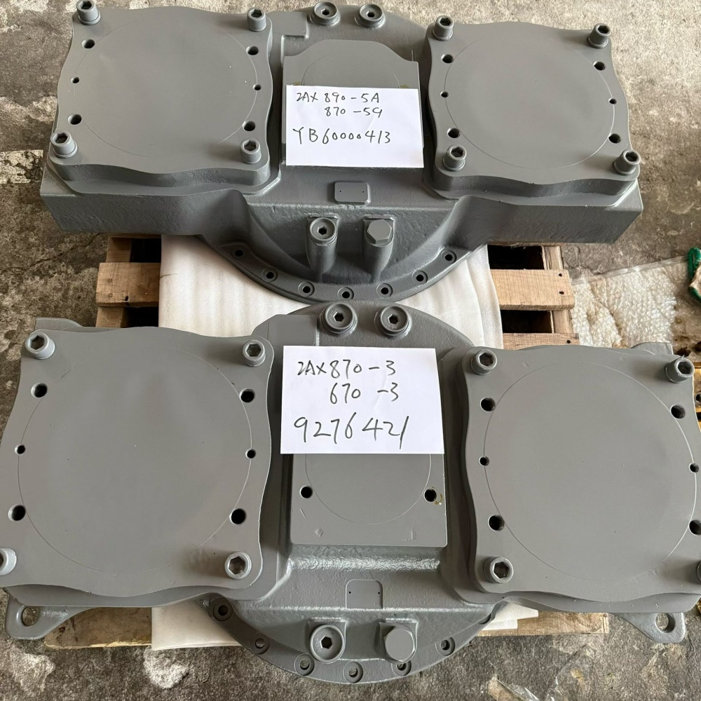
Bir ekskavatör pompa transfer kutusu arızası bir hidrolik pompa sorununu, bir motor sorununu ve hatta bir kontrol sistemi arızasını taklit edebilir. Transfer kutusu, motor çıkışı ile bir veya daha fazla hidrolik pompa arasında yer alır. Görevi mekaniktir: torku kabul etmek, dişliler ve miller aracılığıyla bölmek, bu dönen elemanları yataklar üzerinde desteklemek ve tahrik sistemini hizalı ve yağlanmış tutmaktır. Bu yol üzerindeki herhangi bir kusur gürültü, ısı, metal kalıntı, dengesiz pompa hızı, keçe sızıntısı veya hidrolik gücün tamamen kaybına neden olabilir.
Pahalı hata, arızanın nerede başladığını kanıtlamadan pompaları değiştirmektir. İç hasarlı bir pompa, transfer dişli takımına yük bindirebilir. Aşınmış bir kaplin, girişe darbe uygulayabilir. Arızalı bir yatak, bir dişliyi kavrama dışına çıkarabilir. Düşük veya kirli yağ, aynı anda birden fazla bileşene zarar verebilir. Bu nedenle, profesyonel bir teşhis, çalışma semptomunu basınç verileri, hız verileri, yağlayıcı kanıtları, titreşim konumu, mil durumu, dişli teması, yatak durumu ve gövde geometrisi ile ilişkilendirmelidir.
Bu kılavuz, tamir atölyelerine, filo ekiplerine ve B2B alıcılarına ilk şikayetten kontrollü bir yeniden yapıma ve devreye alma kaydına kadar disiplinli bir yol sunar. Genel mühendislik uygulamalarını açıklar. Makine servis kılavuzu ve tam pompa-transfer kutusu kılavuzu; yağ sınıfı, seviye prosedürü, boşluk, yatak ayarları, açıklıklar, tork, kaldırma ve kabul limitleri için otorite olmaya devam eder.
Pompa transfer kutusunun işlevi
Büyük ekskavatörler genellikle bom, kol, kepçe, dönüş, yürüyüş, soğutma ve pilot fonksiyonlar için önemli miktarda hidrolik güce ihtiyaç duyar. Transfer kutusu, motor ile hidrolik pompalar arasında kompakt bir mekanik bağlantı noktası oluşturur. Bir giriş flanşı, mil veya kaplin motor torkunu alır. Bir dişli takımı daha sonra bu torku pompalara bağlı çıkış millerine iletir. Yataklar mil konumlarını kontrol eder, gövde merkez mesafelerini korur, keçeler yağlayıcıyı tutar ve havalandırma elemanları iç basıncı yönetir.
Bu düzenleme, aynı semptomun neden birkaç farklı sebebi olabileceğini açıklar. Bir çıkış yatağı boşluk geliştirirse, dişli teması kayar ve yük altında gürültü artar. Bir pompa sıkışmaya başlarsa, dişli takımı anormal burulma yükü görür. Giriş kaplini aşınmışsa, dişlileri hâlâ yeniden kullanılabilir olsa bile kutu hasarlı gibi ses çıkarabilir. Yağ seviyesi yanlışsa, görünür diş arızasından önce ısı ve köpüklenme ortaya çıkabilir. Bu nedenle teşhis, motor kaplinini, transfer kutusunu, pompa arayüzlerini ve pompaları tek bir bağlantılı tahrik sistemi olarak ele almalıdır.
The Hitachi pompa şanzıman yağı bilgileri bu tür bir uygulama için yağlama, dişli çalışması, aşınma koruması ve korozyon korumasını vurgular. Bu genel bir noktayı destekler: yağlayıcı bir sarf malzemesi değil, çalışan bir bileşendir. Isı taşır, yüzeyleri ayırır, kirleticileri askıda tutar ve arıza mekanizmasını tanımlayabilecek kanıtları korur.
Sökmeden önce bir kanıt zinciri oluşturun
Operatörün tanımıyla başlayın, ancak bunu tekrarlanabilir koşullara dönüştürün. Şikayetin soğukta mı yoksa sıcakta mı, rölantide mi yoksa yüksek hızda mı, tek bir hidrolik fonksiyonda mı yoksa birkaçında mı, motor hızlanması sırasında mı, pompa debi düşürme sırasında mı yoksa belirli bir onarımdan sonra mı ortaya çıktığını kaydedin. İlk tarihi, makine saatini, son yağ veya pompa çalışmalarını ve semptomun aniden mi ortaya çıktığını yoksa zamanla mı ilerlediğini not edin.
Makineyi temizlemeden önce inceleyin. Sızıntıları, havalandırma durumunu, montaj cıvatalarını, kaplin muhafazalarını, hortum güzergâhını, gövde hasarını ve bağlantı yerlerinin çevresindeki yer değiştirmiş boyayı fotoğraflayın. Sıvı seviyesini üretici prosedürüne göre doğrulayın. Temiz bir yağ numunesi alın ve tahliye yağını ince bir elek üzerinden saklayın. Her numuneyi yağ sıcaklığı, makine saati, numune alma noktası ve çalışma koşulu ile etiketleyin. Karışık, etiketsiz bir numunenin teşhis değeri azdır.
| Kanıt | Kaydedilecekler | Neyi gösterebilir |
|---|---|---|
| Gürültü | Konum, frekans, yük, hız, sıcaklık | Dişli kavraması, yatak, kaplin, pompa pulsasyonu veya rezonans |
| Sıcaklık | Karşılaştırılabilir noktalar ve stabilize çalışma koşulu | Sürtünme, ön yük, düşük yağ, aşırı yük veya kısıtlı ısı atımı |
| Yağlayıcı | Seviye, renk, koku, köpük, su, partikül tipi | Oksidasyon, havalanma, kirlenme, diş veya yatak hasarı |
| Titreşim | Sensör konumu, yönü, hız ve yük | Dengesizlik, gevşeklik, dişli kavraması, yatak kusuru veya yanlış hizalama |
| Hidrolik davranış | Pompa hızı, basınç tepkisi ve etkilenen fonksiyonlar | Pompa yükü, tahrik kesintisi, kontrol sorunu veya çoklu sistem arızası |
Dönen parçaların yakınında asla tornavida veya doğaçlama bir sonda kullanmayın. Makine kilitleme, muhafaza, kaldırma, yangın ve sıcak sıvı prosedürlerine uyun. Dinleme veya titreşim ölçümleri çalıştırmayı gerektiriyorsa, güvenli bir konumdan onaylı cihazlar kullanın. Büyük transfer grupları önemli miktarda kütle depolar ve montajlar veya pompalar söküldüğünde hareket edebilir.
Transfer kutusu semptomlarını hidrolik pompa arızalarından ayırın
Gürültülü bir pompa-transfer bölgesi dişli hasarını kanıtlamaz. Hidrolik basınç dalgalanması gövdeyi uyarabilir. Bir pompa giriş yatağı titreşimi kutuya iletebilir. Bozulmuş bir esnek kaplin hız değişimleri sırasında vurabilir. Bir motor ateşleme veya montaj sorunu, transfer gövdesinde görünen tekrarlayan bir titreşim üretebilir. Teşhis sorusu “Nerede duyuyorum?” değil, “Hangi bileşen enerjiyi üretiyor ve sinyal çalışma durumuna göre nasıl değişiyor?” olmalıdır.”
Mekanik semptomu hidrolik yüklemeyle karşılaştırın. Belirli bir pompa yüklendiğinde gürültü keskin biçimde değişiyorsa, o pompaya bağlı çıkışı tanımlayın. Hidrolik sistem yüksüzken gürültü motor hızını takip ediyorsa, giriş yolunu, yatakları ve dişli kavramasını inceleyin. Bir hidrolik devre zayıfsa ancak ilgili pompa mili beklenen hızda dönüyorsa, transfer kutusunu suçlamadan önce o pompayı ve kontrollerini araştırın. Birkaç pompa çıkışı birlikte düzensizleşiyorsa ve giriş hızı sabitse, ortak bir mekanik tahrik sorunu dikkate değerdir.
Servis prosedürünün izin verdiği durumlarda, motor hızını ve erişilebilir her pompa veya çıkış hızını kalibre edilmiş ekipmanla ölçün. Doğru test noktalarını kullanarak hidrolik basınçları ve kontrol komutlarını inceleyin. Üretici bu prosedürü açıkça sağlamadıkça, yalnızca bir gürültüyü izole etmek için bir pompayı ayırmayın veya kısmen monte edilmiş bir tahriki çalıştırmayın. En güvenli faydalı karşılaştırma genellikle normal testler sırasında senkronize hız, basınç, sıcaklık ve titreşim ölçümlerinden elde edilir.
Sitenin ekskavatör hidrolik pompa spesifikasyon kılavuzu pompanın kendisi şüpheli hale geldiğinde gereken tanımlama verilerini açıklar. İlgili hidrolik pompa tahrik dişlisi inceleme kılavuzu daha dar biçimde dişli kanıtlarına odaklanır. Onarım kapsamının yalnızca en hasarlı parçayı değil, nedeni ele alması için her iki kaydı da transfer kutusu bulgularıyla birlikte kullanın.
Yağlayıcıyı ve kalıntıyı arıza kanıtı olarak kullanın
Yağ durumu, söküm öncesinde aramayı daraltabilir. Düşük seviye sızıntıya, yanlış dolum prosedürüne veya ihmal edilmiş servise işaret edebilir. Köpüklü yağ, tasarıma bağlı olarak havalanma, aşırı dolum, kirlenme veya dönüş çalkalanmasından kaynaklanabilir. Koyu yağ ve yanık koku, aşırı sıcaklık veya uzun süreli oksidasyona işaret eder. Sütlü görünüm suyu gösterebilir; görünür metalik partiküller ise kontrollü inceleme gerektirir.
Manyetik ve manyetik olmayan kalıntıyı ayırın; boyut, şekil, renk ve miktarı belgeleyin. Bir mıknatıs üzerindeki ince demirli pasta, taze pullar veya talaşlardan farklı öneme sahip olabilir. Bakır renkli malzeme bir kafes, baskı yüzeyi veya burçtan gelebilir. Keçe parçaları, boya ve conta malzemesi önceki çalışmaları da ortaya koyabilir. Laboratuvar yağ analizi partikül sayıları, elementel eğilimler, viskozite, su ve oksidasyon verileri ekleyebilir; ancak tek bir numune yağ yaşı, tamamlamalar, filtrasyon ve temel geçmişe göre yorumlanmalıdır.
Neden kaydedilmeden önce tüm kanıtları yıkayıp uzaklaştırmayın. Tersine, her partikülü her dişlinin değiştirilmesi gerektiğinin kanıtı olarak değerlendirmeyin. Konum ve morfoloji önemlidir. Kırılmış bir diş, geniş yapışkan aşınmadan farklı bir desen üretir. Çöken bir yatak, başka türlü kullanılabilir dişliler üzerinden ikincil kalıntı gönderebilir. Kanıt zincirinin amacı, başlatan arızayı ve kalıntısına maruz kalan parçaları tanımlamaktır.
Çalışma incelemesi sırasında yatak üreticileri gürültü, titreşim, sıcaklık ve yağlayıcı durumunun izlenmesini önerir. NSK çalışma incelemesi kılavuzu bu genel gözlemler için faydalıdır; makineye özgü limitleri ise tam ekskavatör kılavuzu sağlar.
Gürültü, sıcaklık ve titreşimi dikkatle yorumlayın
Dişli kavraması, mil hızı ve diş sayısıyla ilişkili karakteristik frekanslar üretir. Yataklar, geometri ve hızla ilişkili tekrarlayan darbe desenleri üretebilir. Gevşeklik harmonikler ve modülasyon oluşturabilir. Bu ilkeler titreşim analizini güçlü kılar; ancak mil hızı referansı, diş sayısı, sensör yönü ve temel veri olmadan bir spektrum yanıltıcı olabilir. İşaretli ölçüm noktalarında ve aynı çalışma durumlarında tekrarlanabilir veri toplayın.
Giri SKF machine-condition guide provides a useful overview of vibration-based machinery diagnosis.
Temperature measurements also need context. Compare like locations with the same load, ambient condition, warm-up period, and instrument settings. A local hot spot near one bearing can be more useful than a single absolute housing temperature. Rising temperature after a rebuild can result from incorrect bearing setting, misalignment, wrong oil, low oil, excessive oil, or an external pump load. Stop the test if the machine procedure or risk assessment requires it.
Plan removal so the evidence survives
Before removal, obtain the machine serial plate, engine identification, transfer-case assembly tag, pump tags, and current parts information. Mark each pump position and each hose, connector, shim pack, bracket, coupling orientation, and support. Photograph the assembly from several directions. Measure accessible shaft end play or flange runout only with an approved method and note the measuring setup.
Support the pumps and transfer case independently before removing fasteners. Do not let a pump hang from a shaft, coupling, pilot, or hose. Cap hydraulic openings immediately with clean compatible caps. Protect machined pilots and splines. Use the specified lifting points and verify the center of gravity. A case that appears stable on a bench can rotate abruptly as covers or pumps are removed.
If the case has locating dowels, shims, selective spacers, or matched bearing components, preserve their original positions. Stamp-free identification tags and compartmented trays reduce assembly errors. Do not punch-mark a precision surface. If contamination is severe, designate a clean teardown area and prevent debris from moving into open hydraulic components.
Inspect gears with measurements, not impressions
Clean components using the approved process and adequate lighting. Inspect every tooth flank, root, tip, and edge. Look for pitting, spalling, scoring, scuffing, cracking, polishing, abnormal contact, plastic flow, corrosion, and impact marks. Examine internal splines, keys, retaining features, shoulders, and oil passages. A visually dramatic mark is not always the initiating failure; the contact pattern and associated bearing evidence must agree.
Measure backlash and gear contact according to the exact manual. Backlash depends on module or diametral pitch, pressure angle, center distance, tooth thickness, temperature, bearing setting, and assembly design. A universal “good” value is unsafe. The KHK gear technical reference explains standard gear geometry and helps technicians understand measurement relationships, but it cannot replace the Hitachi or machine-specific reuse limit.
| Gear observation | Olası katkıda bulunan faktörler | Evidence to seek |
|---|---|---|
| Contact near one edge | Misalignment, housing distortion, bearing movement | Bearing-seat condition, shaft runout, dowels, mounting-face data |
| Scuffing or smeared flank | Lubrication breakdown, overload, wrong oil | Oil history, temperature, load event, companion-tooth damage |
| Repeated pitting | Contact fatigue, surface distress, misload | Pattern location, tooth count, hardness records, alignment |
| Çatlamış veya kırılmış diş | Impact, foreign object, overload, prior fatigue | Fracture origin, debris, coupling event, pump seizure |
| Worn spline | Relative movement, poor engagement, misalignment | Mating spline, engagement length, fretting, shaft support |
When cracks are suspected, use a suitable nondestructive examination method performed by qualified personnel. Record the method, preparation, coverage, indication location, and acceptance criteria. Do not grind away an indication before it is evaluated. Gears that operate as a matched set may require set replacement even if only one member looks damaged; follow the manual and supplier evidence.
Inspect bearings, shafts, and housing as a system
Bearings determine the running position of the gears. Inspect races, rolling elements, cages, seals, and shoulders for flaking, smearing, discoloration, corrosion, indentations, electrical damage, and debris tracks. A failed bearing may be the cause of poor gear contact, or it may be secondary damage from particles generated elsewhere. Document load-zone patterns and correlate them with shaft and housing measurements.
Check shafts for journal wear, scoring, cracks, spline damage, thread damage, runout, and shoulder condition using calibrated tools and the specified support method. Check housings for fretting at bearing seats, spun races, cracks, damaged dowels, distorted mounting faces, blocked oil paths, and previous repair. A new bearing installed in an oversized or distorted seat will not restore alignment.
Measure rather than relying on finger feel. Record tool identification, calibration status, room and component temperature, datum, and repeated readings. Diameters, bores, runout, end play, preload method, shim thickness, and gear contact all form part of one geometry chain. If the housing requires machining or sleeving, the repair provider must preserve shaft center distance, axis relationship, shoulder location, and oil passages. Ask for a dimensional report.
| Bileşen | Minimum inspection record | Decision dependency |
|---|---|---|
| Input and output shafts | Markings, journals, splines, runout, cracks | Manual limits and mating-part condition |
| Bearings | Part marking, load pattern, race/cage condition | Cause analysis, seat fit, contamination exposure |
| Muhafaza | Bores, faces, dowels, cracks, oil paths | Alignment and approved repair method |
| Gears | All flanks, backlash, contact, bore/spline, NDT if required | Matched-set policy and service limits |
| Seals and breather | Lip track, hardness, contamination, blockage | Shaft finish, case pressure, lubricant control |
Find the initiating cause before approving parts
A rebuild report should state a defensible failure sequence. For example: an output bearing seat lost fit, the shaft moved, gear contact shifted toward an edge, tooth loading increased, pitting progressed, and ferrous debris circulated through the case. That sequence leads to a different repair from “gears worn.” It requires housing correction or replacement, bearing and gear evaluation, cleaning of oil passages, and investigation of the load that affected the output.
Another sequence might begin with hydraulic pump seizure or extreme drag. In that case, the transfer case may show torsional damage at splines, coupling, or teeth. Rebuilding the case without repairing the pump repeats the event. A low-oil sequence may require finding the leak or fill error, inspecting every lubricated bearing and gear, and correcting the service procedure. A contamination sequence may require cleaning the case, cooler or passages specified by the design, and any components sharing the oil.
Use a simple causal table during the repair review. Separate confirmed evidence, likely mechanism, alternative explanation, and required proof. This prevents a purchasing decision from being driven by the first damaged part found.
| Confirmed evidence | Working mechanism | Alternative | Next proof |
|---|---|---|---|
| Edge contact plus bearing-seat fretting | Shaft misalignment under load | Housing mounting distortion | Bore alignment and mounting-face measurement |
| Heat and dark oil throughout | Lubrication or sustained overload | External heat source | Oil history, viscosity and load data |
| Broken tooth with impact marks | Foreign object or shock load | Fatigue-origin fracture | Fractography, debris path and event history |
| One output damaged near failed pump | Pump drag transferred into gearing | Transfer bearing caused pump damage | Pump teardown and chronology comparison |
Specify a rebuild that can be audited
A useful rebuild scope lists every inspection, measurement, replacement, approved reuse, machining step, cleaning step, and final test. It identifies the governing manual revision and acceptance limits. It also records who supplied the parts and whether gears, bearings, spacers, and shims must be installed as matched or selective groups.
Replace seals and one-time fasteners where the manual requires them. Do not substitute a bearing based only on nominal bore and outside diameter; internal clearance, precision class, cage, load rating, lubrication, and shoulder geometry may differ. Do not substitute a gear based only on tooth count. Bore, spline, helix, pressure angle, face width, material, heat treatment, tooth modification, and mating member all matter.
For catalog comparison, Hongtengda lists a 9276421-associated pump transfer case assembly ve ayrı bir YB60000413-associated pump transfer case assembly. These listings are useful inquiry references, not proof that two assemblies interchange or fit every machine carrying a similar model name. Differences in serial range, pump interfaces, input flange, sensor or lubrication details, mounting, gear ratio, and revisions must be checked.
Prepare an RFQ that prevents identification errors
A buyer should send the complete machine model and serial number, engine model and serial, transfer-case assembly tag, each hydraulic pump tag, and the requested part number exactly as marked. Add clear photographs of the entire unit, input and output sides, mounting faces, ports, sensors, breathers, couplings, and damage. Include measured shaft or spline data when the old unit is available.
State whether the request is for a complete assembly, bare housing, gear, shaft, bearing kit, seal kit, or rebuild service. Describe the failure and list components already replaced. Ask the supplier to confirm what is included, the identification basis, required core condition, preservation, test documentation, packaging, warranty terms, lead time, and any excluded accessories. Keep confirmation in writing.
For a remanufactured assembly, request the teardown and inspection standard, critical measurements, replacement criteria, housing-repair method, gear and bearing traceability where available, cleaning controls, assembly procedure, and test record. “Rebuilt” alone does not define scope. A professional quotation should let the workshop compare like with like.
| RFQ alanı | Neden önemlidir |
|---|---|
| Machine and engine serial plates | Separates model families, serial breaks, and regional configurations |
| Transfer-case and pump tags | Connects the assembly to its real interfaces |
| Photos of every side | Shows flanges, mounts, ports, sensors, and configuration |
| Arıza kanıtı | Defines contamination risk and repair scope |
| Measured interfaces | Provides a second check when markings are unclear |
| Required deliverables | Clarifies test report, preservation, packaging, and warranty |
Control assembly cleanliness and geometry
Clean the housing, oil galleries, covers, fasteners, magnetic collectors, and reusable components by the approved method. Ensure cleaning media and lint cannot remain inside. Confirm oil passages are open. Keep new bearings and cleaned gears protected until installation. Use the specified assembly lubricant and never rotate a dry bearing under load.
Install bearings with force applied through the correct ring, using controlled heating or tooling where specified. Verify seating against shoulders. Install shafts, gears, spacers, and retaining devices in the recorded sequence. Set preload, end play, and backlash by the manufacturer method. Apply marking compound only as permitted, rotate in the specified direction and load condition, and document the final contact pattern.
Check shaft rotation at defined stages so a problem can be located before the case is closed. Verify seals face the correct direction and run on acceptable surfaces. Use specified sealants sparingly and prevent excess material from entering oil passages. Apply fastener torque and angle in the correct sequence with calibrated tools. Record final values rather than writing only “assembled.”
Commission the rebuilt transfer case in stages
Before installation, confirm the engine coupling and pump inputs are acceptable. Align and support the assembly as the manual directs. Connect pumps without forcing pilots or using fasteners to draw misaligned components together. Route hoses and wiring to avoid stress. Fill with the specified clean lubricant by the correct level and temperature procedure, then complete any priming or pre-lubrication step.
The first run should be controlled. Verify rotation and oil circulation according to the manual. Listen and observe at low-risk conditions, then increase speed and hydraulic load in planned steps. Monitor leakage, oil level, case temperature, vibration, pump speed, and hydraulic response. Stop for abnormal noise, rapid temperature rise, metal generation, loss of drive, or any manual-defined limit.
After stabilization, repeat measurements at the same marked points used before repair. Check for leaks after shutdown and follow the required oil-level procedure. If the manual requires an early oil or filter inspection, perform it and retain the findings. A single quiet idle run is not a commissioning test.
| Aşama | Kaydedin | Decision |
|---|---|---|
| Pre-start | Oil, alignment, mounts, guards, pump connections, manual steps | Ready or correct deficiency |
| Initial rotation | Noise, circulation, leakage, speed | Continue or stop |
| Warm unloaded operation | Temperature trend, vibration, oil condition | Establish stable baseline |
| Staged hydraulic load | Each output response, temperature and vibration | Confirm shared and individual drive behavior |
| Post-test inspection | Leaks, level, debris check, fastener checks if specified | Release, monitor, or reopen |
A practical engineering decision record
The final job file should connect the complaint, pre-removal measurements, oil and debris findings, teardown photographs, dimensional report, root-cause statement, part decisions, assembly settings, and commissioning results. This record protects the workshop and the buyer. It also creates a baseline for future vibration, temperature, and oil trends.
Classify each component as accepted, repaired, replaced, or rejected, and give the supporting evidence. List unresolved risks and required follow-up. If the exact cause cannot be proven, say so and document the most probable mechanism plus the controls used to reduce recurrence. Technical honesty is more useful than false certainty.
For written comparison of an excavator pump transfer case, send Hongtengda the machine serial plate, complete case and pump tags, old-unit photographs, input and output interface details, measured spline information, and the teardown report through the parts inquiry page. The response should confirm the identification basis before price, production, or shipment decisions are treated as final.