An excavator that will not stop, will not start, or stops unexpectedly may have a switch fault, but the control chain also includes power supply, grounds, connectors, relays, harnesses, controllers and an engine shutdown actuator. Replacing the visible switch before tracing that chain can leave the original fault unchanged. This guide presents an excavator engine stop switch test for repair teams and a fitment checklist for parts buyers.
Define whether the fault is start, run or stop
Write the sequence exactly. Does the engine fail to crank, crank without starting, start only while the switch is held, stop during vibration, or continue running after the stop command? Note alarms, monitor messages, battery condition and whether moving the harness changes the symptom. A clear sequence determines which contacts and circuits need testing.
Caterpillar describes a secondary engine shutdown switch as an excavator safety feature in its excavator safety guidance. Switch purpose and logic vary by machine, so distinguish an emergency or secondary shutdown device from a routine key switch, fuel shutoff, limit switch or controller input. Never bypass a safety-related circuit to keep the machine working.
| Symptom | Possible switch-chain issue | Other system to check |
|---|---|---|
| No crank | Open permissive or stop circuit | Battery, key switch, neutral/safety logic, starter circuit |
| Cranks but will not run | Stop input remains active | Fuel supply, engine controller and shutdown actuator |
| Will not shut down | Switch does not change state or signal is lost | Relay, controller output or fuel actuator |
| Stops over bumps | Intermittent contact or connector tension | Harness chafe, loose ground or power interruption |
| Problem changes with temperature | Contact or terminal resistance changes | Relay coil, controller or actuator heat fault |
Make the machine safe before electrical tests
Lower the attachment, apply the specified lockout, stop and isolate the machine as the service procedure requires. The HSE’s maintenance guidance emphasizes safe isolation and competent repair. Identify circuits that must remain powered for live measurements and circuits that must be de-energized for resistance or continuity tests.
Do not pierce sealed wires casually or bridge terminals with loose metal. Use the correct breakout leads, fused jumpers and meter range. Protect connectors from dirt and water. If the switch is part of an emergency shutdown system, restore and function-test the complete safety circuit before returning the machine to service.
Inspect the switch, connector and harness first
Check the lever or plunger for free movement and correct mechanical contact with its stop or bracket. Look for a bent mount, missing actuator tab or a switch that never reaches its full position. Inspect the loom for abrasion, crushing and repairs. Disconnect by the housing, not the wires, and examine terminals for push-back, spread contacts, corrosion, heat or moisture.
TE Connectivity notes that locking features help resist disconnection under vibration and that sealed connector designs support harsh off-road use in its terminal and connector overview. Those are general design principles; the original Hitachi connector, terminal position and circuit diagram govern the repair.
| Inspection point | Normal evidence | Fault evidence |
|---|---|---|
| Mechanical travel | Full repeatable actuation | Binding, bent bracket or incomplete contact |
| Connector latch | Positive engagement | Broken lock or partial mating |
| Terminals | Aligned, clean and retained | Push-back, corrosion, heat or spread contact |
| Loom | Supported away from rub points | Chafe, crushing or tension |
| Ground/power path | Stable under approved load test | Voltage drop or intermittent interruption |
Test contact states against the wiring diagram
Identify common, normally open and normally closed terminals from the machine diagram or verified switch data. With power removed where required, measure the specified terminal pairs in each switch position. Fluke explains that a continuity test verifies a closed circuit and can reveal intermittent opens or shorts, while warning that the circuit should be de-energized for resistance and continuity measurements in its Model 88V user manual.
Do not stop at an audible tone. Record resistance or voltage results as the procedure requires, then repeat while gently moving the connector and loom. For an installed live test, compare supply, ground and output with the switch released and actuated. A correct switch output that never reaches the controller indicates a harness or connector fault. A controller that receives the correct state but does not command shutdown moves the investigation downstream.
Use a voltage-drop test under the approved operating condition when a circuit carries load. An unloaded connector can show battery voltage through a high-resistance path and still fail when a relay or actuator is commanded. Test across the connection or ground path as the wiring diagram requires, and record polarity and reference point. Never use resistance mode on an energized circuit.
If a scan tool or service monitor is available, watch the controller’s switch-state input while actuating the device and moving the harness. A physical switch that changes correctly at its terminals but not in the displayed input points toward wiring, terminal tension or controller-interface problems. A correct displayed input with no shutdown response requires downstream checks rather than another switch.
The video above explicitly covers an engine stop and starting problem on a Tata Hitachi EX210 excavator. It provides relevant machine context, while the wiring diagram and service data for the actual serial number remain authoritative.
Match the complete switch assembly
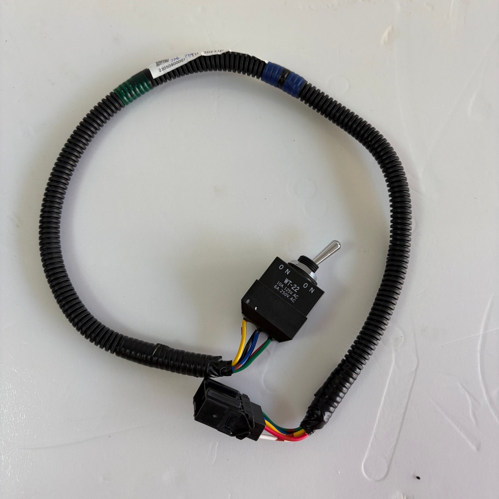
The catalog’s Hitachi engine stop limit switch 4618419 listing shows a switch, short loom and multi-pin connector. Confirm whether the required supply scope is the complete assembly or the switch alone. Compare lever style and length, body dimensions, mounting holes, thread or bracket, contact arrangement, wire colors, loom length, connector keying and terminal count.
Related cab-control parts such as the Hitachi ZX180W-7 throttle dial assembly sit in a different control path and are not substitutes. The switch and instrument category can be used to find enquiry candidates. Send the machine model, complete serial number, original labels and connector photographs through the contact page.
State whether the quotation must include the loom, connector, mounting hardware and protective boot. Ask which number was used for matching and whether the contact logic is normally open, normally closed or multi-pole. Do not accept wire colors alone as a pinout. A receiving inspection should compare connector keys, terminal count, lever travel and loom length before the old assembly is removed from service stock.
| RFQ field | What to send | Purpose |
|---|---|---|
| Machine identity | Model and full serial plate | Separates wiring and production versions |
| Switch identity | Part number, body markings and ratings | Confirms the electrical device |
| Mechanical interface | Lever, bracket, holes and installed position | Prevents actuation mismatch |
| Electrical interface | Connector faces, keying, pins and loom length | Prevents harness mismatch |
| Test record | Contact states, supply, ground and output | Shows whether replacement is justified |
Verify every state before handover
Install the assembly without stretching the loom or changing its protected route. Use the specified fasteners and connector locks. With the attachment safely positioned, verify the normal start sequence, stable running, routine stop and any secondary or emergency shutdown function defined by the manufacturer. Confirm that no diagnostic codes remain and that moving the harness no longer changes the state. Record released, actuated and post-reset results so the repair has an auditable finish.
After the machine reaches operating temperature, repeat the state test because vibration and heat may expose an intermittent terminal or contact. Check that the switch returns mechanically and that the controller recognizes reset in the correct order. Label any separate safety fault still open and keep the machine out of service until the complete shutdown function passes.