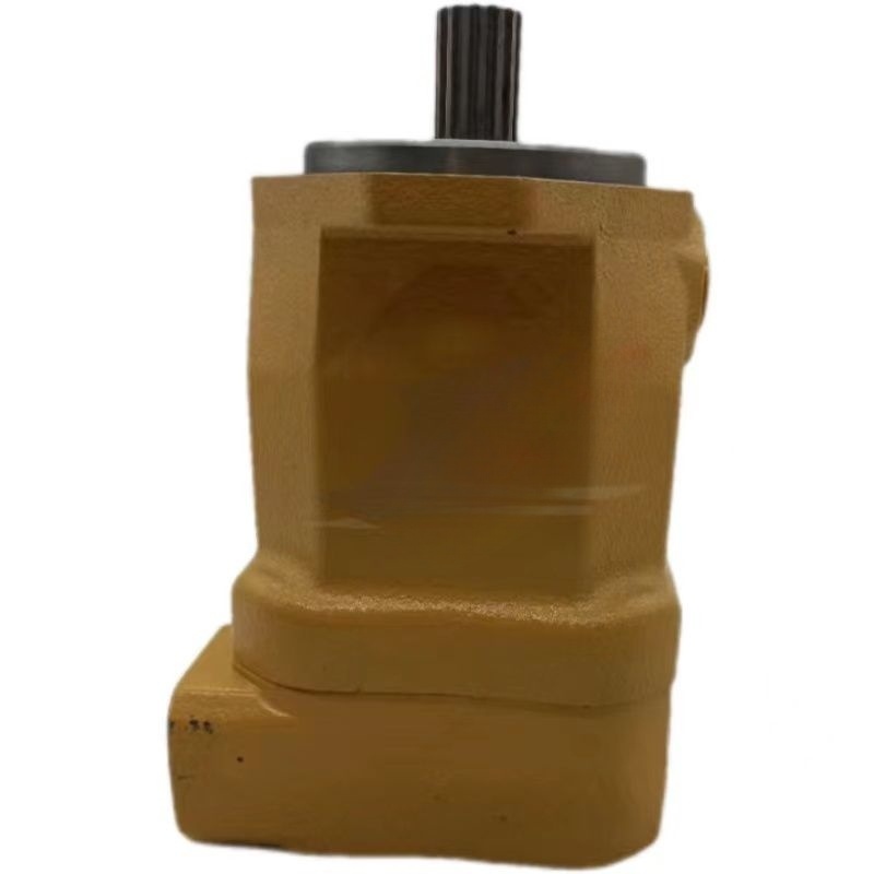
An excavator hydraulic fan pump diagnosis must separate a pump problem from fan motor, cooler, control-valve, sensor, wiring, and airflow faults. A hot-running excavator may have a clean, healthy pump while the radiator is blocked. A slow fan may result from a controller command, proportional valve, motor leakage, belt or coupling arrangement, suction restriction, or incorrect oil. Replacing the fan pump without system evidence can leave the overheat unchanged.
Hydraulic fan drives convert pump flow and pressure into controlled fan speed. Depending on the machine, the system may reverse the fan, modulate speed with temperature, or default to a defined state after an electrical fault. Obtain the serial-specific hydraulic and electrical schematics before testing.
Record the cooling complaint precisely
Note which temperature rises: engine coolant, hydraulic oil, charge air, transmission, or several together. Record ambient temperature, load, engine speed, fan command, actual fan speed, fluid temperatures, and the time required for overheating. Inspect whether the complaint occurs only under travel, digging, lifting, or regeneration.
Save codes and live data. Verify temperature-sensor readings against an independent measurement at the correct point. An incorrect temperature input can command the wrong fan speed even when the hydraulic drive is healthy.
| Observation | Possible direction | Next evidence |
|---|---|---|
| Command high, fan speed low | Pump, motor, valve, restriction, leakage | Pressure, flow, current and motor case drain |
| Command remains low while hot | Sensor, wiring, controller or strategy | Input validation and electrical tests |
| Fan speed normal but temperatures rise | Airflow blockage or cooling-system issue | Cooler inspection and temperature differential |
| Noise or foam | Aeration, suction restriction, low oil | Tank, inlet, filter and oil inspection |
Inspect airflow before hydraulic components
Clean and inspect the radiator, oil cooler, charge-air cooler, screens, fan blades, shroud, guards, and seals. Look for packed debris between stacked cores, damaged fins, missing foam, wrong fan orientation, and air recirculation. Confirm the engine compartment panels are installed as designed.
Check coolant and hydraulic-oil levels and condition by the correct procedure. Inspect coolers internally when pressure drop or contamination is suspected. A fan cannot compensate for restricted coolant circulation or a cooler coated with dust and oil.
Map pump, control, and motor circuits
Identify the fan pump inlet, outlet, case drain, control port, relief or pressure-control elements, directional/reversing valve, fan motor ports, cooler, filter, and tank. On electronically controlled systems, map solenoid supply, ground, command, sensors, and controller pins.
Danfoss’s hydraulic fan-drive technical information shows how purpose-built pump, control, and motor elements form a system. Its values apply to the described Danfoss equipment, not the Caterpillar pump shown here.
Test pump inlet and oil condition
Inspect the tank, breather, suction hose, clamps, strainer if fitted, and inlet fittings. Measure inlet restriction using the specified procedure. A collapsed hose or air leak can cause noise, low flow, heat, and pump damage. Check oil for foam, water, particles, wrong viscosity, and excessive temperature.
Do not run the pump dry after replacement. Follow the required filling and priming procedure. Case-drain routing and allowable backpressure are critical to pump life.
Measure command, pressure, flow, and fan speed together
Use calibrated equipment at the specified test points. Record engine speed, oil temperature, pump outlet pressure, pump flow, fan speed, control current or pressure, and relevant case-drain flows under the same condition. Pressure alone does not prove flow; fan speed alone does not identify whether pump or motor leakage caused a deficit.
Compare commanded and actual response through a controlled temperature or service-tool test. Danfoss’s Series 45 pump information illustrates that fan-drive controls can relate input current to pump pressure. The exact direction and curve vary by control configuration, so never apply generic current values.
| Test | What it supports | What it cannot prove alone |
|---|---|---|
| Pump pressure | Load and control state | Adequate flow or motor efficiency |
| Pump flow | Delivery at defined speed and pressure | Correct controller command |
| Fan speed | Final mechanical response | Which hydraulic component is weak |
| Control current/pressure | Command reaching the pump or valve | Internal actuator movement |
| Case drain | Internal leakage under set conditions | Cooling-core airflow |
Separate fan pump from fan motor faults
If pump flow is below specification at the correct drive speed, inlet condition, oil temperature, load, and command, investigate pump wear or control failure. If pump delivery is correct but motor speed is low and motor case drain is excessive, the motor becomes more likely. If both hydraulic units test correctly, inspect fan mechanics and airflow.
The excavator hydraulic fan motor diagnosis guide provides the motor-side evidence path. Test the complete loop before purchasing either component.
Inspect and identify the pump correctly
Hongtengda lists a CAT345C fan pump associated with 266-8034 and a separate CAT365C fan-pump listing. Similar application descriptions do not prove interchangeability.
Send machine model and serial, engine arrangement, complete pump tag, old part number, shaft spline, pilot diameter, mounting pattern, rotation, all port sizes and positions, control-valve and connector details, and photographs of every side. Include pressure, flow, fan-speed, command, case-drain, oil, and contamination results.
Install and commission the replacement
Correct the initiating fault, clean affected lines and coolers, replace required filters, and verify tank cleanliness. Fill or prime the pump as instructed. Align the drive without forcing the shaft. Connect each hose and control line to the documented port and maintain clean caps until connection.
Start at the specified low-risk condition. Check oil supply, noise, leakage, case pressure, command, outlet pressure, flow, and fan direction. Warm the system gradually and verify fan speed across commanded states. Confirm engine coolant and hydraulic-oil temperatures stabilize under the original load.
The main pump regulator guide explains pressure-flow-control evidence in more detail. For fan-pump comparison, submit the complete machine, pump, interface, and test record through the Hongtengda parts inquiry page.