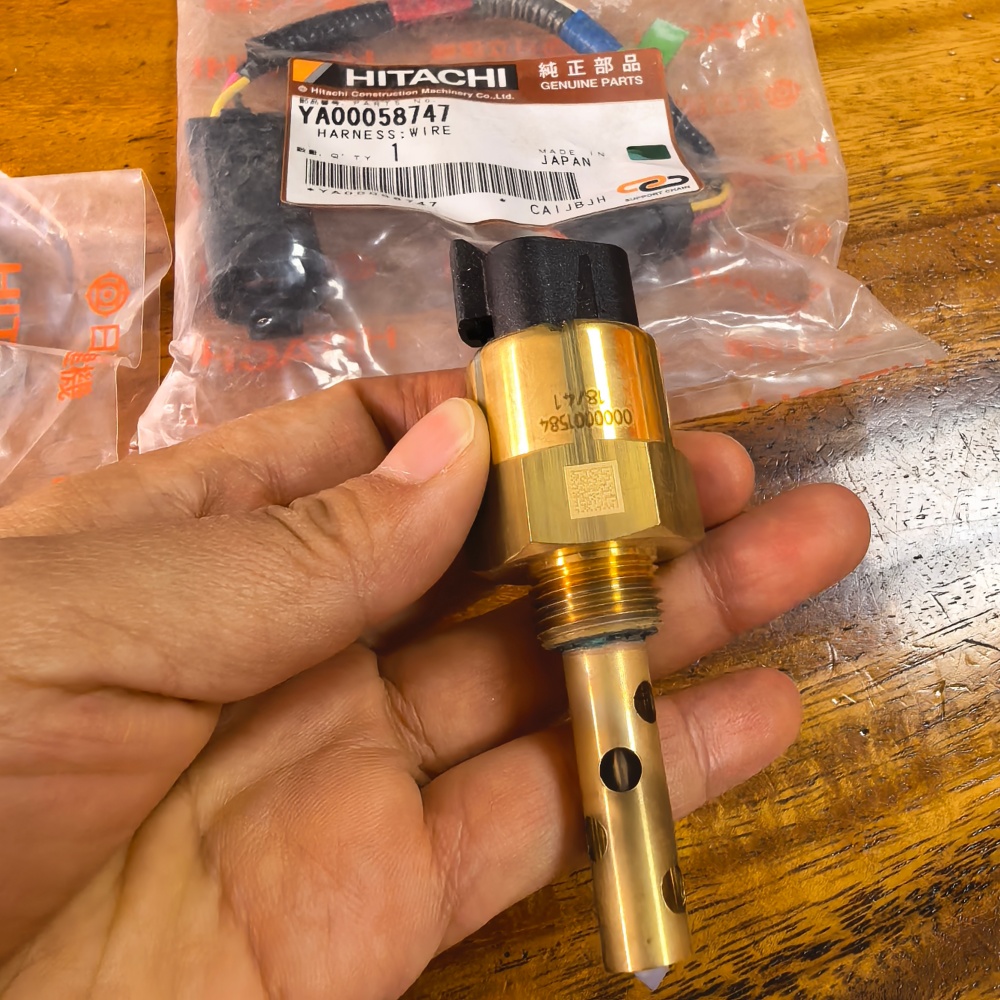
An excavator transfer case oil level sensor diagnosis must first confirm whether the oil is genuinely low. A warning can come from leakage, an incorrect level-check procedure, machine slope, temperature, foaming, delayed drain-back, contaminated oil, a stuck sensing element, poor ground, connector resistance, damaged harness, or controller input. Replacing the sensor before checking the mechanical condition can leave expensive gears and bearings without adequate lubrication.
This guide focuses on transfer cases that drive hydraulic pumps on large excavators. Always use the machine manual for the correct oil, fill point, level method, temperature condition, sensor logic, circuit values, pressure release, torque, and acceptance limits.
Confirm the oil level by the official procedure
Park the machine on the specified level surface, position the attachment safely, shut down, release pressure, and wait the required drain-back time. Use the defined sight gauge, dipstick, inspection plug, or service-tool procedure. Record oil temperature and machine attitude. A valid electronic comparison needs a valid manual level check.
Inspect for leaks at seals, shafts, covers, plugs, breathers, hoses, coolers, and sensor threads. Check for recent service errors or the wrong fill volume. Do not add oil merely to silence a warning; overfilling can cause churning, aeration, heat, leakage, and misleading level behavior.
Hitachi’s pump transmission oil information highlights lubrication, gear operation, viscosity, corrosion protection, and seal compatibility. The exact EX1200-5 instruction manual determines the required product and procedure.
Identify sensor type and warning logic
Level devices can operate as simple switches or produce a variable signal. They can be normally open or normally closed and may change state as level rises or falls. TE Connectivity’s liquid-level switch overview shows several general configurations and explains that orientation and switch logic vary.
Do not assume the Hitachi component uses the same technology. Obtain the serial-specific electrical schematic, connector view, sensor test, controller logic, and installation orientation. Identify power, ground, signal, shared reference, and any harness intermediate connectors.
Hongtengda lists a level sensor associated with YA00058748 and a harness reference YA00058747. These numbers and the product image are inquiry evidence, not universal fitment proof.
Record warning behavior before disturbing the circuit
Note whether the warning appears at key-on, immediately after start, during travel, on a slope, only when hot, or intermittently over rough ground. Record transfer-case temperature, actual oil level, machine position, operating hours, recent repairs, and diagnostic codes.
| Warning pattern | Possible direction | Next proof |
|---|---|---|
| Constant warning with correct level | Sensor state, open/short circuit, connector or controller | Circuit-state test at sensor and controller |
| Warning only on slopes | Oil movement, low margin, mounting orientation | Level procedure and operating-angle guidance |
| Warning after hot shutdown | Drain-back, aeration, temperature-sensitive circuit | Timed level and electrical measurements |
| Intermittent warning over vibration | Loose connector, harness chafe, sensing-element movement | Visual inspection and controlled wiggle test |
| Low level confirmed repeatedly | Leak, wrong fill, consumption or service problem | Leak tracing and oil-accounting record |
Inspect oil condition and transfer-case health
Check oil color, odor, foam, water, and particles by the approved method. Retain a labeled sample if contamination is suspected. A low-level warning accompanied by noise, heat, or debris demands mechanical investigation, not only electrical testing.
Inspect the breather and case pressure controls. A blocked breather can promote leakage or affect seals. Verify that the case has the correct oil and that mixed or wrong-viscosity fluid has not changed drain-back or foaming behavior. Follow the site’s pump transfer case failure guide when mechanical symptoms are present.
Inspect the sensor and harness
Release pressure and prevent hot-oil exposure. Clean the area before disconnecting the sensor. Inspect the connector lock, seals, terminal tension, corrosion, oil entry, harness clamps, chafing, heat damage, and previous splices. Trace the catalog-associated harness rather than assuming the short lead is the complete circuit.
Photograph the sensor orientation, thread engagement, sealing method, and connector before removal. Inspect the sensing portion for sludge, varnish, debris, damage, and blocked openings. Do not probe, bend, or force the sensing element. Keep the case opening capped and prevent dirt entry.
Test the electrical circuit using the schematic
Identify expected circuit states from the manual. Use approved breakout leads and test at both the sensor and controller when required. Verify supply and ground under load for a powered device. For a switch circuit, compare continuity or voltage state at known oil conditions only through the specified procedure.
Never jumper terminals blindly. A guessed bypass can short a controller reference or suppress a real low-oil warning. Do not apply battery voltage to the sensor. If a resistance test is specified, isolate the component exactly as instructed and compare with the correct temperature and state.
| Test point | Question answered | Limit of the result |
|---|---|---|
| Manual oil-level check | Is the case actually at the specified level? | Does not prove electrical operation |
| Sensor output at connector | Does state correspond to the test condition? | Does not prove signal reaches controller |
| Controller-pin measurement | Does the complete harness deliver the state? | Does not prove controller software response |
| Harness voltage drop | Is resistance excessive under load? | Does not prove sensing element moves correctly |
| Scan-tool status | How does the controller interpret the input? | Does not prove the physical level is safe |
Distinguish a sensor fault from real level movement
Compare the warning with repeated manual checks at the same temperature and machine attitude. If the physical level changes, find the leak or transfer path. If the level remains correct and the sensor output changes unexpectedly, capture the circuit during vibration and temperature changes.
Foam and turbulence can affect some sensing arrangements. A warning during operation that disappears after drain-back may be meaningful or may reflect an installation issue; only the machine documentation can decide. Do not change sensor depth or orientation to suppress the warning.
Install the verified component cleanly
Confirm part number, thread, sealing surface, connector, harness, and orientation before installation. Use the specified seal and never add tape or general-purpose sealant unless authorized. Tighten to the prescribed torque with the sensor supported correctly. Route and clamp the harness away from heat, vibration, and sharp edges.
Restore the oil using the specified product and level procedure. Inspect for leakage before and after warm operation. If the case was opened or drained, complete any priming or circulation step required by the manufacturer.
Verify the warning system after repair
Use the official functional test to confirm warning activation and clearing. Check key-on behavior, scan-tool status, connector stability, and the original operating condition. Recheck actual oil level after shutdown and drain-back. Confirm no leaks and no new codes.
If the system supports event history, verify the fault does not return. A repaired wire or replacement sensor is not enough when the case continues to lose oil. Include follow-up inspection intervals when the initiating leak or contamination required broader work.
Prepare a precise level-sensor RFQ
Send the machine model and serial number, transfer-case assembly tag, sensor marking, harness number, connector face, wire colors and count, thread and sealing photographs, installed orientation, and warning codes. Include actual oil-level checks and circuit results.
Ask the supplier to confirm sensor function, normal state, connector, thread, sealing parts, harness inclusion, calibration or orientation requirement, and serial-fitment basis. The pump drive gear inspection guide can support a mechanical damage review if low oil produced debris.
Send the full evidence package through the Hongtengda parts inquiry page. A complete record lets the buyer distinguish a genuine low-level event from a sensor, harness, or installation problem before shipment and installation.