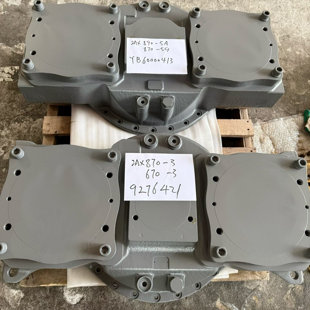
Один неисправность раздаточной коробки насоса экскаватора может имитировать проблему гидравлического насоса, проблему двигателя или даже неисправность системы управления. Раздаточная коробка расположена между выходом двигателя и одним или несколькими гидравлическими насосами. Её задача — механическая: воспринимать крутящий момент, распределять его через шестерни и валы, поддерживать эти вращающиеся элементы на подшипниках и обеспечивать соосность и смазку трансмиссии. Дефект в любом месте этого пути может вызвать шум, нагрев, металлические частицы, нестабильную частоту вращения насоса, утечку через уплотнения или полную потерю гидравлической мощности.
Дорогостоящая ошибка — заменять насосы, не доказав, где начинается неисправность. Насос с внутренними повреждениями может нагружать зубчатую передачу раздаточной коробки. Изношенная муфта может создавать ударную нагрузку на вход. Отказавший подшипник может вывести шестерню из зацепления. Низкий уровень или загрязнённое масло могут повредить несколько компонентов одновременно. По этой причине профессиональная диагностика должна связывать эксплуатационный симптом с данными давления, данными частоты вращения, состоянием смазки, локализацией вибрации, состоянием валов, контактом зубьев, состоянием подшипников и геометрией корпуса.
Данное руководство даёт ремонтным мастерским, паркам техники и B2B-покупателям дисциплинированный путь от первой жалобы до контролируемого восстановления и протокола ввода в эксплуатацию. Оно описывает общую инженерную практику. Руководство по обслуживанию машины и точное руководство по насосно-раздаточной коробке остаются определяющими для марки масла, процедуры проверки уровня, бокового зазора, настроек подшипников, зазоров, момента затяжки, подъёма и критериев приёмки.
Назначение раздаточной коробки насоса
Большим экскаваторам часто требуется значительная гидравлическая мощность для функций стрелы, рукояти, ковша, поворота, передвижения, охлаждения и пилотных функций. Раздаточная коробка создаёт компактное механическое соединение между двигателем и гидравлическими насосами. Входной фланец, вал или муфта воспринимают крутящий момент двигателя. Зубчатый набор затем передаёт этот крутящий момент на выходные валы, соединённые с насосами. Подшипники контролируют положение валов, корпус сохраняет межцентровые расстояния, уплотнения удерживают смазку, а сапуны регулируют внутреннее давление.
Такая компоновка объясняет, почему один и тот же симптом может иметь несколько причин. Если выходной подшипник приобретает люфт, контакт зубьев смещается и шум возрастает под нагрузкой. Если насос начинает заклинивать, зубчатая передача испытывает аномальную крутильную нагрузку. Если входная муфта изношена, корпус может звучать как повреждённый, даже когда его шестерни остаются пригодными к использованию. Если уровень масла неправильный, нагрев и вспенивание могут появиться до видимого разрушения зубьев. Поэтому диагностика должна рассматривать муфту двигателя, раздаточную коробку, интерфейсы насосов и насосы как единую связанную приводную систему.
The Информация о трансмиссионном масле насоса Hitachi подчёркивает смазку, работу зубчатых передач, защиту от износа и защиту от коррозии для данного типа применения. Это подтверждает общий принцип: смазка является рабочим компонентом, а не просто расходным материалом. Она отводит тепло, разделяет поверхности, удерживает загрязнения и сохраняет свидетельства, позволяющие идентифицировать механизм отказа.
Построение цепочки доказательств до разборки
Начните с описания оператора, но преобразуйте его в условия, которые можно воспроизвести. Зафиксируйте, возникает ли жалоба на холодную или на горячую, на холостом ходу или на высокой скорости, с одной гидравлической функцией или несколькими, при ускорении двигателя, при сбросе насоса или после конкретного ремонта. Отметьте первую дату, моточасы, недавние работы с маслом или насосом, а также появился ли симптом внезапно или прогрессировал со временем.
Осмотрите машину до очистки. Сфотографируйте утечки, состояние сапуна, крепёжные болты, кожухи муфт, прокладку шлангов, повреждения корпуса и смещённую краску вокруг соединений. Подтвердите уровень жидкости согласно процедуре производителя. Отберите чистую пробу масла и сохраните слитое масло через мелкое сито. Промаркируйте каждую пробу с указанием температуры масла, моточасов, точки отбора и рабочих условий. Смешанная немаркированная проба имеет малую диагностическую ценность.
| Доказательства | Что записывать | На что это может указывать |
|---|---|---|
| Шум | Локализация, частота, нагрузка, скорость, температура | Зацепление зубьев, подшипник, муфта, пульсация насоса или резонанс |
| Температура | Сопоставимые точки и стабилизированный рабочий режим | Трение, предварительный натяг, низкий уровень масла, перегрузка или ограниченный отвод тепла |
| Смазка | Уровень, цвет, запах, пена, вода, тип частиц | Окисление, аэрация, загрязнение, повреждение зубьев или подшипников |
| Вибрации | Расположение датчика, направление, скорость и нагрузка | Дисбаланс, ослабление, зацепление зубьев, дефект подшипника или несоосность |
| Гидравлическое поведение | Частота вращения насоса, реакция давления и затронутые функции | Нагрузка насоса, прерывание привода, проблема управления или неисправность нескольких систем |
Никогда не используйте отвёртку или самодельный щуп рядом с вращающимися частями. Соблюдайте процедуры блокировки машины, ограждения, подъёма, пожарной безопасности и работы с горячей жидкостью. Если для прослушивания или измерения вибрации требуется работа машины, используйте утверждённые приборы из безопасного места. Крупные раздаточные сборки обладают значительной массой и могут сместиться при снятии опор или насосов.
Отделение симптомов раздаточной коробки от неисправностей гидравлического насоса
Шум в зоне насосно-раздаточной коробки не доказывает повреждение зубьев. Пульсация гидравлического давления может возбуждать корпус. Входной подшипник насоса может передавать вибрацию в корпус. Разрушенная гибкая муфта может стучать при изменении скорости. Проблема воспламенения или опоры двигателя может создавать повторяющуюся вибрацию, проявляющуюся на корпусе раздаточной коробки. Диагностический вопрос не “Где я это слышу?”, а “Какой компонент создаёт энергию и как сигнал изменяется в зависимости от рабочего состояния?”
Сравните механический симптом с гидравлической нагрузкой. Если шум резко изменяется при нагружении конкретного насоса, определите выход, соединённый с этим насосом. Если он следует за частотой вращения двигателя при ненагруженной гидравлической системе, проверьте входной тракт, подшипники и зацепление зубьев. Если один гидравлический контур слаб, но соответствующий вал насоса вращается с ожидаемой скоростью, исследуйте этот насос и его управление, прежде чем осуждать раздаточную коробку. Если несколько выходов насосов становятся нестабильными одновременно, а входная скорость стабильна, проблема общего механического привода заслуживает внимания.
Там, где процедура обслуживания это допускает, измеряйте частоту вращения двигателя и каждого доступного насоса или выходного вала с помощью калиброванного оборудования. Проверяйте гидравлические давления и команды управления, используя правильные точки подключения. Не отключайте насос и не эксплуатируйте частично собранный привод только для изоляции шума, если производитель явно не предусматривает такую процедуру. Наиболее безопасное полезное сравнение часто получают из синхронизированных измерений скорости, давления, температуры и вибрации во время нормальных испытаний.
Руководство сайта по спецификациям гидравлического насоса экскаватора объясняет идентификационные данные, необходимые когда сам насос становится подозреваемым. Связанное руководство по inspection приводной шестерни гидравлического насоса фокусируется более узко на свидетельствах состояния зубьев. Используйте оба документа вместе с результатами по раздаточной коробке, чтобы объём ремонта устранял причину, а не только наиболее повреждённую деталь.
Использование смазки и частиц как свидетельств отказа
Состояние масла может сузить поиск до разборки. Низкий уровень может указывать на утечку, неправильную процедуру заправки или запущенное обслуживание. Вспененное масло может быть результатом аэрации, перелива, загрязнения или перемешивания при возврате, в зависимости от конструкции. Тёмное масло и запах горелого указывают на чрезмерную температуру или длительное окисление. Молочный вид может указывать на воду, а видимые металлические частицы требуют контролируемого осмотра.
Разделяйте магнитные и немагнитные частицы и документируйте размер, форму, цвет и количество. Мелкая ферромагнитная паста на магните может отличаться по значимости от свежих чешуек или стружки. Материал медного цвета может происходить от сепаратора, упорной поверхности или втулки. Фрагменты уплотнений, краска и материал прокладок также могут выявить предыдущие работы. Лабораторный анализ масла может добавить подсчёт частиц, элементные тренды, вязкость, воду и данные окисления, но одна проба должна интерпретироваться с учётом возраста масла, доливок, фильтрации и базовой истории.
Не смывайте все свидетельства до фиксации причины. И наоборот, не рассматривайте каждую частицу как доказательство того, что все шестерни должны быть заменены. Расположение и морфология имеют значение. Скол зуба создаёт иной паттерн, чем широкий адгезионный износ. Разрушающийся подшипник может направить вторичные частицы через otherwise пригодные шестерни. Цель цепочки доказательств — идентифицировать инициирующий отказ и детали, подвергшиеся воздействию его частиц.
При эксплуатационном осмотре производители подшипников рекомендуют следить за шумом, вибрацией, температурой и состоянием смазки. Руководство NSK по эксплуатационному осмотру полезно для этих общих наблюдений, тогда как точное руководство по экскаватору предоставляет специфические для машины пределы.
Тщательная интерпретация шума, температуры и вибрации
Зацепление зубьев создаёт характерные частоты, связанные со скоростью вала и числом зубьев. Подшипники могут создавать повторяющиеся ударные паттерны, связанные с геометрией и скоростью. Ослабление может создавать гармоники и модуляцию. Эти принципы делают вибрационный анализ мощным, но спектр без привязки к скорости вала, числу зубьев, ориентации датчика и базовой линии может вводить в заблуждение. Собирайте воспроизводимые данные в маркированных точках измерения и при одинаковых рабочих состояниях.
Сравнивайте входную сторону, каждую выходную сторону и корпус вблизи посадочных мест подшипников. Записывайте осевое, горизонтальное и вертикальное направления, когда это практически возможно. Широкое увеличение высокочастотной энергии может сопровождать нарушение смазки; дискретная компонента зацепления с боковыми полосами может указывать на модуляцию; сильная компонента рабочей скорости может указывать на дисбаланс или несоосность. Это диагностические зацепки, а не автоматические решения о замене. SKF machine-condition guide provides a useful overview of vibration-based machinery diagnosis.
Temperature measurements also need context. Compare like locations with the same load, ambient condition, warm-up period, and instrument settings. A local hot spot near one bearing can be more useful than a single absolute housing temperature. Rising temperature after a rebuild can result from incorrect bearing setting, misalignment, wrong oil, low oil, excessive oil, or an external pump load. Stop the test if the machine procedure or risk assessment requires it.
Plan removal so the evidence survives
Before removal, obtain the machine serial plate, engine identification, transfer-case assembly tag, pump tags, and current parts information. Mark each pump position and each hose, connector, shim pack, bracket, coupling orientation, and support. Photograph the assembly from several directions. Measure accessible shaft end play or flange runout only with an approved method and note the measuring setup.
Support the pumps and transfer case independently before removing fasteners. Do not let a pump hang from a shaft, coupling, pilot, or hose. Cap hydraulic openings immediately with clean compatible caps. Protect machined pilots and splines. Use the specified lifting points and verify the center of gravity. A case that appears stable on a bench can rotate abruptly as covers or pumps are removed.
If the case has locating dowels, shims, selective spacers, or matched bearing components, preserve their original positions. Stamp-free identification tags and compartmented trays reduce assembly errors. Do not punch-mark a precision surface. If contamination is severe, designate a clean teardown area and prevent debris from moving into open hydraulic components.
Inspect gears with measurements, not impressions
Clean components using the approved process and adequate lighting. Inspect every tooth flank, root, tip, and edge. Look for pitting, spalling, scoring, scuffing, cracking, polishing, abnormal contact, plastic flow, corrosion, and impact marks. Examine internal splines, keys, retaining features, shoulders, and oil passages. A visually dramatic mark is not always the initiating failure; the contact pattern and associated bearing evidence must agree.
Measure backlash and gear contact according to the exact manual. Backlash depends on module or diametral pitch, pressure angle, center distance, tooth thickness, temperature, bearing setting, and assembly design. A universal “good” value is unsafe. The KHK gear technical reference explains standard gear geometry and helps technicians understand measurement relationships, but it cannot replace the Hitachi or machine-specific reuse limit.
| Gear observation | Возможные причины | Evidence to seek |
|---|---|---|
| Contact near one edge | Misalignment, housing distortion, bearing movement | Bearing-seat condition, shaft runout, dowels, mounting-face data |
| Scuffing or smeared flank | Lubrication breakdown, overload, wrong oil | Oil history, temperature, load event, companion-tooth damage |
| Repeated pitting | Contact fatigue, surface distress, misload | Pattern location, tooth count, hardness records, alignment |
| Трещина или излом зуба | Impact, foreign object, overload, prior fatigue | Fracture origin, debris, coupling event, pump seizure |
| Worn spline | Relative movement, poor engagement, misalignment | Mating spline, engagement length, fretting, shaft support |
When cracks are suspected, use a suitable nondestructive examination method performed by qualified personnel. Record the method, preparation, coverage, indication location, and acceptance criteria. Do not grind away an indication before it is evaluated. Gears that operate as a matched set may require set replacement even if only one member looks damaged; follow the manual and supplier evidence.
Inspect bearings, shafts, and housing as a system
Bearings determine the running position of the gears. Inspect races, rolling elements, cages, seals, and shoulders for flaking, smearing, discoloration, corrosion, indentations, electrical damage, and debris tracks. A failed bearing may be the cause of poor gear contact, or it may be secondary damage from particles generated elsewhere. Document load-zone patterns and correlate them with shaft and housing measurements.
Check shafts for journal wear, scoring, cracks, spline damage, thread damage, runout, and shoulder condition using calibrated tools and the specified support method. Check housings for fretting at bearing seats, spun races, cracks, damaged dowels, distorted mounting faces, blocked oil paths, and previous repair. A new bearing installed in an oversized or distorted seat will not restore alignment.
Measure rather than relying on finger feel. Record tool identification, calibration status, room and component temperature, datum, and repeated readings. Diameters, bores, runout, end play, preload method, shim thickness, and gear contact all form part of one geometry chain. If the housing requires machining or sleeving, the repair provider must preserve shaft center distance, axis relationship, shoulder location, and oil passages. Ask for a dimensional report.
| Компонент | Minimum inspection record | Decision dependency |
|---|---|---|
| Input and output shafts | Markings, journals, splines, runout, cracks | Manual limits and mating-part condition |
| Bearings | Part marking, load pattern, race/cage condition | Cause analysis, seat fit, contamination exposure |
| Корпус | Bores, faces, dowels, cracks, oil paths | Alignment and approved repair method |
| Gears | All flanks, backlash, contact, bore/spline, NDT if required | Matched-set policy and service limits |
| Seals and breather | Lip track, hardness, contamination, blockage | Shaft finish, case pressure, lubricant control |
Find the initiating cause before approving parts
A rebuild report should state a defensible failure sequence. For example: an output bearing seat lost fit, the shaft moved, gear contact shifted toward an edge, tooth loading increased, pitting progressed, and ferrous debris circulated through the case. That sequence leads to a different repair from “gears worn.” It requires housing correction or replacement, bearing and gear evaluation, cleaning of oil passages, and investigation of the load that affected the output.
Another sequence might begin with hydraulic pump seizure or extreme drag. In that case, the transfer case may show torsional damage at splines, coupling, or teeth. Rebuilding the case without repairing the pump repeats the event. A low-oil sequence may require finding the leak or fill error, inspecting every lubricated bearing and gear, and correcting the service procedure. A contamination sequence may require cleaning the case, cooler or passages specified by the design, and any components sharing the oil.
Use a simple causal table during the repair review. Separate confirmed evidence, likely mechanism, alternative explanation, and required proof. This prevents a purchasing decision from being driven by the first damaged part found.
| Confirmed evidence | Working mechanism | Alternative | Next proof |
|---|---|---|---|
| Edge contact plus bearing-seat fretting | Shaft misalignment under load | Housing mounting distortion | Bore alignment and mounting-face measurement |
| Heat and dark oil throughout | Lubrication or sustained overload | External heat source | Oil history, viscosity and load data |
| Broken tooth with impact marks | Foreign object or shock load | Fatigue-origin fracture | Fractography, debris path and event history |
| One output damaged near failed pump | Pump drag transferred into gearing | Transfer bearing caused pump damage | Pump teardown and chronology comparison |
Specify a rebuild that can be audited
A useful rebuild scope lists every inspection, measurement, replacement, approved reuse, machining step, cleaning step, and final test. It identifies the governing manual revision and acceptance limits. It also records who supplied the parts and whether gears, bearings, spacers, and shims must be installed as matched or selective groups.
Replace seals and one-time fasteners where the manual requires them. Do not substitute a bearing based only on nominal bore and outside diameter; internal clearance, precision class, cage, load rating, lubrication, and shoulder geometry may differ. Do not substitute a gear based only on tooth count. Bore, spline, helix, pressure angle, face width, material, heat treatment, tooth modification, and mating member all matter.
For catalog comparison, Hongtengda lists a 9276421-associated pump transfer case assembly и отдельную YB60000413-associated pump transfer case assembly. These listings are useful inquiry references, not proof that two assemblies interchange or fit every machine carrying a similar model name. Differences in serial range, pump interfaces, input flange, sensor or lubrication details, mounting, gear ratio, and revisions must be checked.
Prepare an RFQ that prevents identification errors
A buyer should send the complete machine model and serial number, engine model and serial, transfer-case assembly tag, each hydraulic pump tag, and the requested part number exactly as marked. Add clear photographs of the entire unit, input and output sides, mounting faces, ports, sensors, breathers, couplings, and damage. Include measured shaft or spline data when the old unit is available.
State whether the request is for a complete assembly, bare housing, gear, shaft, bearing kit, seal kit, or rebuild service. Describe the failure and list components already replaced. Ask the supplier to confirm what is included, the identification basis, required core condition, preservation, test documentation, packaging, warranty terms, lead time, and any excluded accessories. Keep confirmation in writing.
For a remanufactured assembly, request the teardown and inspection standard, critical measurements, replacement criteria, housing-repair method, gear and bearing traceability where available, cleaning controls, assembly procedure, and test record. “Rebuilt” alone does not define scope. A professional quotation should let the workshop compare like with like.
| Поле запроса коммерческого предложения | Почему это важно |
|---|---|
| Machine and engine serial plates | Separates model families, serial breaks, and regional configurations |
| Transfer-case and pump tags | Connects the assembly to its real interfaces |
| Photos of every side | Shows flanges, mounts, ports, sensors, and configuration |
| Доказательства отказа | Defines contamination risk and repair scope |
| Measured interfaces | Provides a second check when markings are unclear |
| Required deliverables | Clarifies test report, preservation, packaging, and warranty |
Control assembly cleanliness and geometry
Clean the housing, oil galleries, covers, fasteners, magnetic collectors, and reusable components by the approved method. Ensure cleaning media and lint cannot remain inside. Confirm oil passages are open. Keep new bearings and cleaned gears protected until installation. Use the specified assembly lubricant and never rotate a dry bearing under load.
Install bearings with force applied through the correct ring, using controlled heating or tooling where specified. Verify seating against shoulders. Install shafts, gears, spacers, and retaining devices in the recorded sequence. Set preload, end play, and backlash by the manufacturer method. Apply marking compound only as permitted, rotate in the specified direction and load condition, and document the final contact pattern.
Check shaft rotation at defined stages so a problem can be located before the case is closed. Verify seals face the correct direction and run on acceptable surfaces. Use specified sealants sparingly and prevent excess material from entering oil passages. Apply fastener torque and angle in the correct sequence with calibrated tools. Record final values rather than writing only “assembled.”
Commission the rebuilt transfer case in stages
Before installation, confirm the engine coupling and pump inputs are acceptable. Align and support the assembly as the manual directs. Connect pumps without forcing pilots or using fasteners to draw misaligned components together. Route hoses and wiring to avoid stress. Fill with the specified clean lubricant by the correct level and temperature procedure, then complete any priming or pre-lubrication step.
The first run should be controlled. Verify rotation and oil circulation according to the manual. Listen and observe at low-risk conditions, then increase speed and hydraulic load in planned steps. Monitor leakage, oil level, case temperature, vibration, pump speed, and hydraulic response. Stop for abnormal noise, rapid temperature rise, metal generation, loss of drive, or any manual-defined limit.
After stabilization, repeat measurements at the same marked points used before repair. Check for leaks after shutdown and follow the required oil-level procedure. If the manual requires an early oil or filter inspection, perform it and retain the findings. A single quiet idle run is not a commissioning test.
| Стадия | Зафиксируйте | Decision |
|---|---|---|
| Pre-start | Oil, alignment, mounts, guards, pump connections, manual steps | Ready or correct deficiency |
| Initial rotation | Noise, circulation, leakage, speed | Continue or stop |
| Warm unloaded operation | Temperature trend, vibration, oil condition | Establish stable baseline |
| Staged hydraulic load | Each output response, temperature and vibration | Confirm shared and individual drive behavior |
| Post-test inspection | Leaks, level, debris check, fastener checks if specified | Release, monitor, or reopen |
A practical engineering decision record
The final job file should connect the complaint, pre-removal measurements, oil and debris findings, teardown photographs, dimensional report, root-cause statement, part decisions, assembly settings, and commissioning results. This record protects the workshop and the buyer. It also creates a baseline for future vibration, temperature, and oil trends.
Classify each component as accepted, repaired, replaced, or rejected, and give the supporting evidence. List unresolved risks and required follow-up. If the exact cause cannot be proven, say so and document the most probable mechanism plus the controls used to reduce recurrence. Technical honesty is more useful than false certainty.
For written comparison of an excavator pump transfer case, send Hongtengda the machine serial plate, complete case and pump tags, old-unit photographs, input and output interface details, measured spline information, and the teardown report through the parts inquiry page. The response should confirm the identification basis before price, production, or shipment decisions are treated as final.